
Page 96 - Automotive Engineering Powertrain Chassis System and Vehicle Body
P. 96
CH AP TER 4 .1 Digital engine control systems
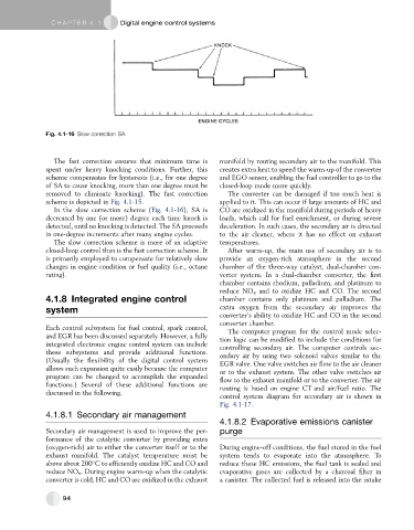
Fig. 4.1-16 Slow correction SA.
The fast correction ensures that minimum time is manifold by routing secondary air to the manifold. This
spent under heavy knocking conditions. Further, this creates extra heat to speed the warm-up of the converter
scheme compensates for hysteresis (i.e., for one degree and EGO sensor, enabling the fuel controller to go to the
of SA to cause knocking, more than one degree must be closed-loop mode more quickly.
removed to eliminate knocking). The fast correction The converter can be damaged if too much heat is
scheme is depicted in Fig. 4.1-15. applied to it. This can occur if large amounts of HC and
In the slow correction scheme (Fig. 4.1-16), SA is CO are oxidized in the manifold during periods of heavy
decreased by one (or more) degree each time knock is loads, which call for fuel enrichment, or during severe
detected, until no knocking is detected. The SA proceeds deceleration. In such cases, the secondary air is directed
in one-degree increments after many engine cycles. to the air cleaner, where it has no effect on exhaust
The slow correction scheme is more of an adaptive temperatures.
closed-loop control than is the fast correction scheme. It After warm-up, the main use of secondary air is to
is primarily employed to compensate for relatively slow provide an oxygen-rich atmosphere in the second
changes in engine condition or fuel quality (i.e., octane chamber of the three-way catalyst, dual-chamber con-
rating). verter system. In a dual-chamber converter, the first
chamber contains rhodium, palladium, and platinum to
reduce NO x and to oxidize HC and CO. The second
4.1.8 Integrated engine control chamber contains only platinum and palladium. The
system extra oxygen from the secondary air improves the
converter’s ability to oxidize HC and CO in the second
converter chamber.
Each control subsystem for fuel control, spark control, The computer program for the control mode selec-
and EGR has been discussed separately. However, a fully tion logic can be modified to include the conditions for
integrated electronic engine control system can include controlling secondary air. The computer controls sec-
these subsystems and provide additional functions. ondary air by using two solenoid valves similar to the
(Usually the flexibility of the digital control system EGR valve. One valve switches air flow to the air cleaner
allows such expansion quite easily because the computer or to the exhaust system. The other valve switches air
program can be changed to accomplish the expanded flow to the exhaust manifold or to the converter. The air
functions.) Several of these additional functions are routing is based on engine CT and air/fuel ratio. The
discussed in the following.
control system diagram for secondary air is shown in
Fig. 4.1-17.
4.1.8.1 Secondary air management
4.1.8.2 Evaporative emissions canister
Secondary air management is used to improve the per- purge
formance of the catalytic converter by providing extra
(oxygen-rich) air to either the converter itself or to the During engine-off conditions, the fuel stored in the fuel
exhaust manifold. The catalyst temperature must be system tends to evaporate into the atmosphere. To
above about 200 C to efficiently oxidize HC and CO and reduce these HC emissions, the fuel tank is sealed and
reduce NO x . During engine warm-up when the catalytic evaporative gases are collected by a charcoal filter in
converter is cold, HC and CO are oxidized in the exhaust a canister. The collected fuel is released into the intake
94