Page 91 - Automotive Engineering Powertrain Chassis System and Vehicle Body
P. 91

Digital engine control systems    CHAPTER 4.1


                                                                           ROM LOOK-UP TABLE

                           MAF
                                                                          SA S     SA P     SA T
                                                                 A/B
                        POS/RPM
                                              CONTROLLER
                                                                  D/B
                          CT


                          TPS


                                                                TRIGGER
                                               ELECTRONIC       PULSES         DRIVER
                                               IGNITION
                                                                               CIRCUITRY
                                               SYSTEM
                                                                            P 1          P 2
                                                             SPARK
                                                             PLUGS
                                                                             S 1         S 2


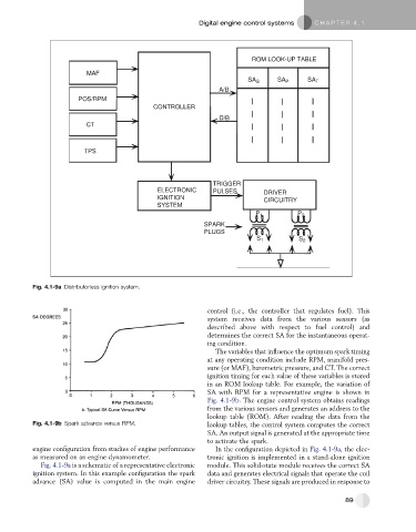
           Fig. 4.1-9a Distributorless ignition system.


                                                              control (i.e., the controller that regulates fuel). This
                                                              system receives data from the various sensors (as
                                                              described above with respect to fuel control) and
                                                              determines the correct SA for the instantaneous operat-
                                                              ing condition.
                                                                The variables that influence the optimum spark timing
                                                              at any operating condition include RPM, manifold pres-
                                                              sure (or MAF), barometric pressure, and CT. The correct
                                                              ignition timing for each value of these variables is stored
                                                              in an ROM lookup table. For example, the variation of
                                                              SA with RPM for a representative engine is shown in
                                                              Fig. 4.1-9b. The engine control system obtains readings
                                                              from the various sensors and generates an address to the
                                                              lookup table (ROM). After reading the data from the
           Fig. 4.1-9b Spark advance versus RPM.              lookup tables, the control system computes the correct
                                                              SA. An output signal is generated at the appropriate time
                                                              to activate the spark.
           engine configuration from studies of engine performance  In the configuration depicted in Fig. 4.1-9a, the elec-
           as measured on an engine dynamometer.              tronic ignition is implemented in a stand-alone ignition
             Fig. 4.1-9a is a schematic of a representative electronic  module. This solid-state module receives the correct SA
           ignition system. In this example configuration the spark  data and generates electrical signals that operate the coil
           advance (SA) value is computed in the main engine  driver circuitry. These signals are produced in response to


                                                                                                       89
   86   87   88   89   90   91   92   93   94   95   96