
Page 87 - Automotive Engineering Powertrain Chassis System and Vehicle Body
P. 87
Digital engine control systems CHAPTER 4.1
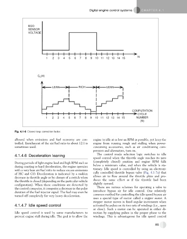
EGO
SENSOR
VOLTAGE
N
1 2 3 4 5 6 7 8 9 10 11 12 13 14 15
C (H)
L
LEAN RICH LEAN
COMPUTATION
CYCLE
1 2 3 4 5 6 7 8 9 10 11 12 13 14 15 NUMBER
(N)
Fig. 4.1-6 Closed-loop correction factor.
allowed when emissions and fuel economy are con- engine to idle at as low an RPM as possible, yet keep the
trolled. Enrichment of the air/fuel ratio to about 12:1 is engine from running rough and stalling when power-
sometimes used. consuming accessories, such as air conditioning com-
pressors and alternators, turn on.
4.1.4.6 Deceleration leaning The control mode selection logic switches to idle
speed control when the throttle angle reaches its zero
During periods of light engine load and high RPM such as (completely closed) position and engine RPM falls
during coasting or hard deceleration, the engine operates below a minimum value, and when the vehicle is sta-
with a very lean air/fuel ratio to reduce excess emissions tionary. Idle speed is controlled by using an electroni-
of HC and CO. Deceleration is indicated by a sudden cally controlled throttle bypass valve (Fig. 4.1-7a) that
decrease in throttle angle or by closure of a switch when allows air to flow around the throttle plate and pro-
the throttle is closed (depending on the particular vehicle duces the same effect as if the throttle had been
configuration). When these conditions are detected by slightly opened.
the control computer, it computes a decrease in the pulse There are various schemes for operating a valve to
duration of the fuel injector signal. The fuel may even be introduce bypass air for idle control. One relatively
turned off completely for very heavy deceleration. common method for controlling the idle speed bypass air
uses a special type of motor called a stepper motor. A
stepper motor moves in fixed angular increments when
4.1.4.7 Idle speed control activated by pulses on its two sets of windings (i.e., open
or close). Such a motor can be operated in either di-
Idle speed control is used by some manufacturers to rection by supplying pulses in the proper phase to the
prevent engine stall during idle. The goal is to allow the windings. This is advantageous for idle speed control
85