
Page 90 - Automotive Engineering Powertrain Chassis System and Vehicle Body
P. 90
CH AP TER 4 .1 Digital engine control systems
ENGINE OIL
I S
ENGINE UNDER HELICAL
CONTROL PRESSURE GEAR
SOLENOID
TO
CONTROL EXHAUST
VALVE CAMSHAFT
POSITION
SENSOR
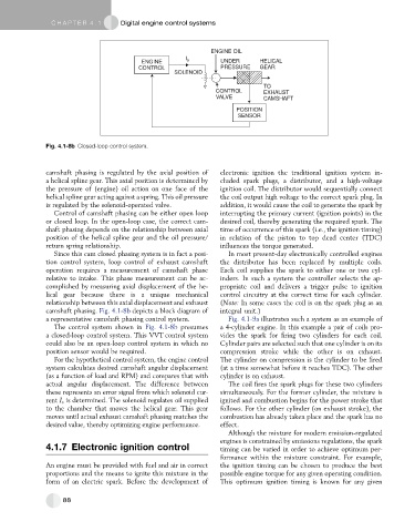
Fig. 4.1-8b Closed-loop control system.
camshaft phasing is regulated by the axial position of electronic ignition the traditional ignition system in-
a helical spline gear. This axial position is determined by cluded spark plugs, a distributor, and a high-voltage
the pressure of (engine) oil action on one face of the ignition coil. The distributor would sequentially connect
helical spline gear acting against a spring. This oil pressure the coil output high voltage to the correct spark plug. In
is regulated by the solenoid-operated valve. addition, it would cause the coil to generate the spark by
Control of camshaft phasing can be either open loop interrupting the primary current (ignition points) in the
or closed loop. In the open-loop case, the correct cam- desired coil, thereby generating the required spark. The
shaft phasing depends on the relationship between axial time of occurrence of this spark (i.e., the ignition timing)
position of the helical spline gear and the oil pressure/ in relation of the piston to top dead center (TDC)
return spring relationship. influences the torque generated.
Since this cam closed phasing system is in fact a posi- In most present-day electronically controlled engines
tion control system, loop control of exhaust camshaft the distributor has been replaced by multiple coils.
operation requires a measurement of camshaft phase Each coil supplies the spark to either one or two cyl-
relative to intake. This phase measurement can be ac- inders. In such a system the controller selects the ap-
complished by measuring axial displacement of the he- propriate coil and delivers a trigger pulse to ignition
lical gear because there is a unique mechanical control circuitry at the correct time for each cylinder.
relationship between this axial displacement and exhaust (Note: In some cases the coil is on the spark plug as an
camshaft phasing. Fig. 4.1-8b depicts a block diagram of integral unit.)
a representative camshaft phasing control system. Fig. 4.1-9a illustrates such a system as an example of
The control system shown in Fig. 4.1-8b presumes a 4-cylinder engine. In this example a pair of coils pro-
a closed-loop control system. This VVT control system vides the spark for firing two cylinders for each coil.
could also be an open-loop control system in which no Cylinder pairs are selected such that one cylinder is on its
position sensor would be required. compression stroke while the other is on exhaust.
For the hypothetical control system, the engine control The cylinder on compression is the cylinder to be fired
system calculates desired camshaft angular displacement (at a time somewhat before it reaches TDC). The other
(as a function of load and RPM) and compares that with cylinder is on exhaust.
actual angular displacement. The difference between The coil fires the spark plugs for these two cylinders
these represents an error signal from which solenoid cur- simultaneously. For the former cylinder, the mixture is
rent I s is determined. The solenoid regulates oil supplied ignited and combustion begins for the power stroke that
to the chamber that moves the helical gear. This gear follows. For the other cylinder (on exhaust stroke), the
moves until actual exhaust camshaft phasing matches the combustion has already taken place and the spark has no
desired value, thereby optimizing engine performance. effect.
Although the mixture for modern emission-regulated
engines is constrained by emissions regulations, the spark
4.1.7 Electronic ignition control timing can be varied in order to achieve optimum per-
formance within the mixture constraint. For example,
An engine must be provided with fuel and air in correct the ignition timing can be chosen to produce the best
proportions and the means to ignite this mixture in the possible engine torque for any given operating condition.
form of an electric spark. Before the development of This optimum ignition timing is known for any given
88