
Page 95 - Automotive Engineering Powertrain Chassis System and Vehicle Body
P. 95
Digital engine control systems CHAPTER 4.1
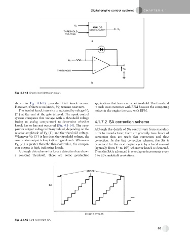
Fig. 4.1-14 Knock level detector circuit.
shown in Fig. 4.1-13, provided that knock occurs. applications that have a variable threshold. The threshold
However, if there is no knock, V K remains near zero. in such cases increases with RPM because the competing
The level of knock intensity is indicated by voltage V K noises in the engine increase with RPM.
(T ) at the end of the gate interval. The spark control
system compares this voltage with a threshold voltage
(using an analog comparator) to determine whether 4.1.7.2 SA correction scheme
knock has or has not occurred (Fig. 4.1-14). The com-
parator output voltage is binary valued, depending on the Although the details of SA control vary from manufac-
relative amplitude of V K (T ) and the threshold voltage. turer to manufacturer, there are generally two classes of
Whenever V K (T ) is less than the threshold voltage, the correction that are used: fast correction and slow
comparator output is low, indicating no knock. Whenever correction. In the fast correction scheme, the SA is
V K (T ) is greater than the threshold value, the compar- decreased for the next engine cycle by a fixed amount
ator output is high, indicating knock. (typically from 5 to 10 ) whenever knock is detected.
Although this scheme for knock detection has shown Then the SA is advanced in one-degree increments every
a constant threshold, there are some production 5 to 20 crankshaft revolutions.
Fig. 4.1-15 Fast correction SA.
93