
Page 92 - Automotive Engineering Powertrain Chassis System and Vehicle Body
P. 92
CH AP TER 4 .1 Digital engine control systems
timing inputs coming from crankshaft and camshaft sig- loop control is that it cannot automatically compensate
nals (POS/RPM). for mechanical changes in the system. Closed-loop
The coil driver circuits generate the primary current in control of ignition timing is desirable from the standpoint
windings P 1 and P 2 of the coil packs depicted in Fig. 4.1- of improving engine performance and maintaining that
9a. These primary currents build up during the so-called performance in spite of system changes.
dwell period before the spark is to occur. At the correct One scheme for closed-loop ignition timing is based
time the driver circuits interrupt the primary currents via on the improvement in performance that is achieved by
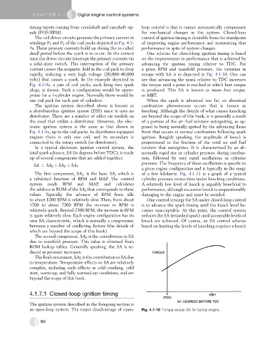
a solid-state switch. This interruption of the primary advancing the ignition timing relative to TDC. For
current causes the magnetic field in the coil pack to drop a given RPM and manifold pressure, the variation in
rapidly, inducing a very high voltage (20,000–40,000 torque with SA is as depicted in Fig. 4.1-10. One can
volts) that causes a spark. In the example depicted in see that advancing the spark relative to TDC increases
Fig. 4.1-9a, a pair of coil packs, each firing two spark the torque until a point is reached at which best torque
plugs, is shown. Such a configuration would be appro- is produced. This SA is known as mean best torque,
priate for a 4-cylinder engine. Normally there would be or MBT.
one coil pack for each pair of cylinders. When the spark is advanced too far, an abnormal
The ignition system described above is known as combustion phenomenon occurs that is known as
a distributorless ignition system (DIS) since it uses no knocking. Although the details of what causes knocking
distributor. There are a number of older car models on are beyond the scope of this book, it is generally a result
the road that utilize a distributor. However, the elec- of a portion of the air–fuel mixture autoigniting, as op-
tronic ignition system is the same as that shown in posed to being normally ignited by the advancing flame
Fig. 4.1-9a, up to the coil packs. In distributor-equipped front that occurs in normal combustion following spark
engines there is only one coil, and its secondary is ignition. Roughly speaking, the amplitude of knock is
connected to the rotary switch (or distributor). proportional to the fraction of the total air and fuel
In a typical electronic ignition control system, the mixture that autoignites. It is characterized by an ab-
total spark advance, SA (in degrees before TDC), is made normally rapid rise in cylinder pressure during combus-
up of several components that are added together: tion, followed by very rapid oscillations in cylinder
pressure. The frequency of these oscillations is specific to
SA ¼ SA S þ SA P þ SA T
a given engine configuration and is typically in the range
The first component, SA S , is the basic SA, which is of a few kilohertz. Fig. 4.1-11 is a graph of a typical
a tabulated function of RPM and MAP. The control cylinder pressure versus time under knocking conditions.
system reads RPM and MAP, and calculates A relatively low level of knock is arguably beneficial to
the address in ROM of the SA S that corresponds to these performance, although excessive knock is unquestionably
values. Typically, the advance of RPM from idle damaging to the engine and must be avoided.
to about 1200 RPM is relatively slow. Then, from about One control strategy for SA under closed-loop control
1200 to about 2300 RPM the increase in RPM is is to advance the spark timing until the knock level be-
relatively quick. Beyond 2300 RPM, the increase in RPM comes unacceptable. At this point, the control system
is again relatively slow. Each engine configuration has its reduces the SA (retarded spark) until acceptable levels of
own SA characteristic, which is normally a compromise knock are achieved. Of course, an SA control scheme
between a number of conflicting factors (the details of based on limiting the levels of knocking requires a knock
which are beyond the scope of this book).
The second component, SA P , is the contribution to SA
due to manifold pressure. This value is obtained from
ROM lookup tables. Generally speaking, the SA is re-
duced as pressure increases.
The final component, SA T , is the contribution to SA due
to temperature. Temperature effects on SA are relatively
complex, including such effects as cold cranking, cold
start, warm-up, and fully warmed-up conditions, and are
beyond the scope of this book.
4.1.7.1 Closed-loop ignition timing
The ignition system described in the foregoing section is
an open-loop system. The major disadvantage of open- Fig. 4.1-10 Torque versus SA for typical engine.
90