
Page 88 - Automotive Engineering Powertrain Chassis System and Vehicle Body
P. 88
CH AP TER 4 .1 Digital engine control systems
b
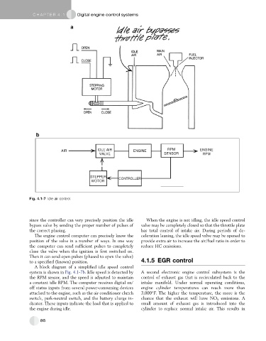
AIR IDLE AIR ENGINE RPM ENGINE
VALVE SENSOR RPM
STEPPER
CONTROLLER
MOTOR
Fig. 4.1-7 Idle air control.
since the controller can very precisely position the idle When the engine is not idling, the idle speed control
bypass valve by sending the proper number of pulses of valve may be completely closed so that the throttle plate
the correct phasing. has total control of intake air. During periods of de-
The engine control computer can precisely know the celeration leaning, the idle speed valve may be opened to
position of the valve in a number of ways. In one way provide extra air to increase the air/fuel ratio in order to
the computer can send sufficient pulses to completely reduce HC emissions.
close the valve when the ignition is first switched on.
Then it can send open pulses (phased to open the valve)
to a specified (known) position. 4.1.5 EGR control
A block diagram of a simplified idle speed control
system is shown in Fig. 4.1-7b. Idle speed is detected by A second electronic engine control subsystem is the
the RPM sensor, and the speed is adjusted to maintain control of exhaust gas that is recirculated back to the
a constant idle RPM. The computer receives digital on/ intake manifold. Under normal operating conditions,
off status inputs from several power-consuming devices engine cylinder temperatures can reach more than
attached to the engine, such as the air conditioner clutch 3,000 F. The higher the temperature, the more is the
switch, park-neutral switch, and the battery charge in- chance that the exhaust will have NO x emissions. A
dicator. These inputs indicate the load that is applied to small amount of exhaust gas is introduced into the
the engine during idle. cylinder to replace normal intake air. This results in
86