Page 85 - Automotive Engineering Powertrain Chassis System and Vehicle Body
P. 85

Digital engine control systems    CHAPTER 4.1


                                               ROM
                                               TABLES


                                            CONTROLLER


                                  TPS
                                                             IGNITION
                                    MIXTURE
                                            FUEL  MIXTURE
                         MAP                INJEC-
                                            TION                                              3WCC
                               THROTTLE                      ENGINE
                                                                             HEGO       DP
                                                                              EGR
                                                                              VALVE
                                                                                        EGR
                                                                                        SIGNAL


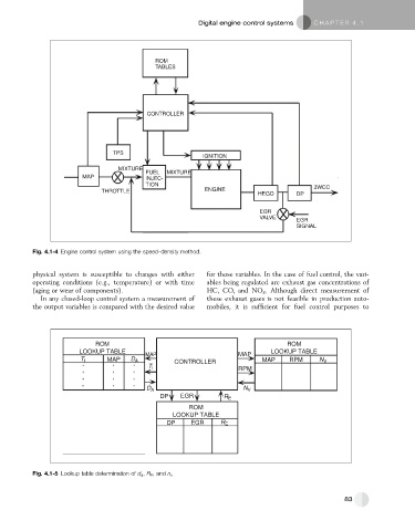
           Fig. 4.1-4 Engine control system using the speed–density method.


           physical system is susceptible to changes with either  for those variables. In the case of fuel control, the vari-
           operating conditions (e.g., temperature) or with time  ables being regulated are exhaust gas concentrations of
           (aging or wear of components).                     HC, CO, and NO x . Although direct measurement of
             In any closed-loop control system a measurement of  these exhaust gases is not feasible in production auto-
           the output variables is compared with the desired value  mobiles, it is sufficient for fuel control purposes to


                             ROM                                                      ROM
                        LOOKUP TABLE                                             LOOKUP TABLE
                                            MAP                        MAP
                         T I     MAP    D A         CONTROLLER                MAP     RPM      N V
                                             T I                       RPM


                                            D A                          N V
                                                DP    EGR          R E
                                                         ROM
                                                    LOOKUP TABLE
                                                  DP     EGR      R E


           Fig. 4.1-5 Lookup table determination of d a , R E , and n v.


                                                                                                       83
   80   81   82   83   84   85   86   87   88   89   90