
Page 89 - Automotive Engineering Powertrain Chassis System and Vehicle Body
P. 89
Digital engine control systems CHAPTER 4.1
lower combustion temperatures, which reduces NO x then commands the correct EGR valve position to
emissions. achieve the desired amount of EGR.
The control mode selection logic determines when
EGR is turnedoffor on. EGRis turned offduring cranking,
cold engine temperature (engine warm-up), idling, accel- 4.1.6 Variable valve timing control
eration, or other conditions demanding high torque.
Since EGR was first introduced as a concept for re- An earlier work introduced the concept and relative
ducing NO x exhaust emissions, its implementation has benefits of variable valve timing for improved volumetric
gone through considerable change. There are in fact many efficiency. There it was explained that performance im-
schemes and configurations for EGR realization. We provement and emissions reductions could be achieved if
discuss here one method of EGR implementation that the opening and closing times (and ideally the valve lift)
incorporates enough features to be representative of all of both intake and exhaust valves could be controlled as
schemes in use today and in the near future. a function of operating conditions. The mechanism for
Fundamental to all EGR schemes is a passageway or varying camshaft phasing, which is in production in cer-
port connecting the exhaust and intake manifolds. A tain vehicles, is used for varying exhaust camshaft phas-
valve is positioned along this passageway whose position ing. This system improves volumetric efficiency by
regulates EGR from zero to some maximum value. varying valve overlap from exhaust closing to intake
Typically, the valve is operated by a diaphragm connected opening. In addition to improving volumetric efficiency,
to a variable vacuum source. The controller operates this variable valve phasing can achieve desired EGR
a solenoid in a periodic variable-duty-cycle mode. The fraction.
average level of vacuum on the diaphragm varies with the The amount of valve overlap is directly related to the
duty cycle. By varying this duty cycle, the control system relative exhaust-intake camshaft phasing. Generally,
has proportional control over the EGR valve opening and minimal overlap is desired at idle. The desired optimal
thereby over the amount of EGR. amount of overlap is determined during engine de-
In many EGR control systems the controller monitors velopment as a function of RPM and load (e.g., by engine
the DP between the exhaust and intake manifold via mapping).
a differential pressure sensor (DPS). With the signal The desired exhaust camshaft phasing is stored in
from this sensor the controller can calculate the valve memory (ROM) in the engine control system as
opening for the desired EGR level. The amount of EGR a function of RPM and load. Then during engine oper-
required is a predetermined function of the load on the ation the correct camshaft phasing can be found via
engine (i.e., power produced). table lookup and interpolation based on measurements
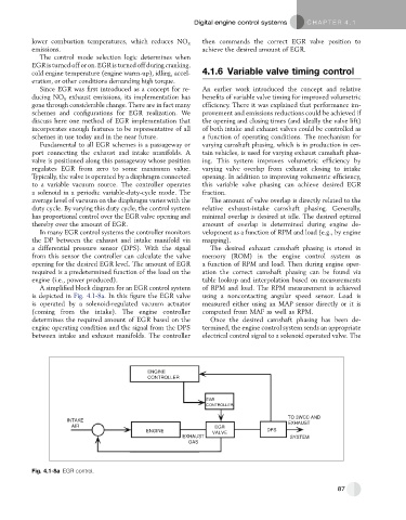
A simplified block diagram for an EGR control system of RPM and load. The RPM measurement is achieved
is depicted in Fig. 4.1-8a. In this figure the EGR valve using a noncontacting angular speed sensor. Load is
is operated by a solenoid-regulated vacuum actuator measured either using an MAP sensor directly or it is
(coming from the intake). The engine controller computed from MAF as well as RPM.
determines the required amount of EGR based on the Once the desired camshaft phasing has been de-
engine operating condition and the signal from the DPS termined, the engine control system sends an appropriate
between intake and exhaust manifolds. The controller electrical control signal to a solenoid operated valve. The
ENGINE
CONTROLLER
EGR
CONTROLLER
TO 3WCC AND
INTAKE
EXHAUST
AIR EGR
ENGINE VALVE DPS
EXHAUST SYSTEM
GAS
Fig. 4.1-8a EGR control.
87