
Page 103 - Automotive Engineering Powertrain Chassis System and Vehicle Body
P. 103
Digital engine control systems CHAPTER 4.1
BATTERY EP POWER
PACK LVB ELECTRONICS
(HVB) EP
MP MP
ICE EM T/A
CLUTCH CLUTCH
C
C 1 2
(a)
BATTERY LVB POWER EP
PACK ELECTRONICS HVB EM
DW
C 2 MP
CLUTCH AXLE
ICE COUPLER T/A
MP MP
C AXLE
1
(b) DW
Fig. 4.1-21 Parallel hybrid schematic.
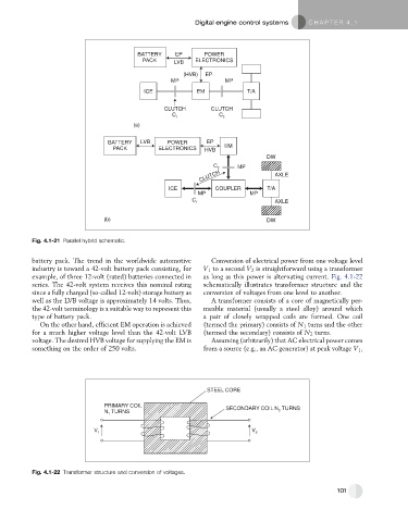
battery pack. The trend in the worldwide automotive Conversion of electrical power from one voltage level
industry is toward a 42-volt battery pack consisting, for V 1 to a second V 2 is straightforward using a transformer
example, of three 12-volt (rated) batteries connected in as long as this power is alternating current. Fig. 4.1-22
series. The 42-volt system receives this nominal rating schematically illustrates transformer structure and the
since a fully charged (so-called 12-volt) storage battery as conversion of voltages from one level to another.
well as the LVB voltage is approximately 14 volts. Thus, A transformer consists of a core of magnetically per-
the 42-volt terminology is a suitable way to represent this meable material (usually a steel alloy) around which
type of battery pack. a pair of closely wrapped coils are formed. One coil
On the other hand, efficient EM operation is achieved (termed the primary) consists of N 1 turns and the other
for a much higher voltage level than the 42-volt LVB (termed the secondary) consists of N 2 turns.
voltage. The desired HVB voltage for supplying the EM is Assuming (arbitrarily) that AC electrical power comes
something on the order of 250 volts. from a source (e.g., an AC generator) at peak voltage V 1 ,
STEEL CORE
PRIMARY COIL SECONDARY COIL N TURNS
N TURNS 2
1
V 1 V 2
Fig. 4.1-22 Transformer structure and conversion of voltages.
101