
Page 128 - Automotive Engineering Powertrain Chassis System and Vehicle Body
P. 128
CH AP TER 5 .1 Transmissions and driveline
operation that may either limit the gears that can be
Table 5.1-1 Typical ratio set
selected or hold a particular gear in order to provide safe
Gear Ratio Gear Ratio operation. These are detected and appropriate actions
invoked by the Automatic Transmission Control Unit
1 3.474 4 0.854 (ATCU).
2 1.948 5 0.685
3 1.247 Reverse 2.714 5.1.4.6 ATCU the controller
ATs have been operated for many years with a hydraulic
Reverse gear (not shown) – drive is obtained through system providing both the logic and control actuating
the sun of epicyclic A with the carrier locked. This ro- functions. The development of digital controllers and the
tates the annulus in the opposite direction to the sun at necessary parallel development of low-cost sensors, and
a value just below half the primary speed. This is still electrical actuators have allowed the control logic to be
subject to the reduction epicyclic ratio. implemented digitally. This allows considerably in-
A set of manufacturer’s ratios through the main sec- creased functionality together with greater flexibility and
tion of the transmission (excluding final drive ratio) is adaptability of the controller, overall the classic combi-
given in Table 5.1-1. nation of electronic ‘brain’ with hydraulic ‘muscle’.
A block diagram showing the basic controller inputs
5.1.4.5 Shift strategy and outputs for the JF506E is shown in Fig. 5.1-24.
There are also interconnections through the CAN bus,
The basic ratio selection depends on a pre-determined most importantly to not only the engine management,
shift strategy but there are also many subtleties in the but also brakes and the instrument pack. The flexibility
way that changes are executed. The strategy is funda- of the bus system means that the path is open for in-
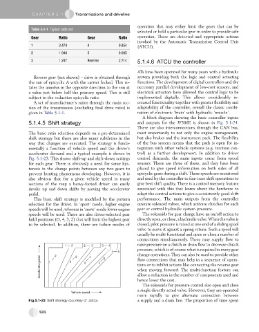
mentally a function of vehicle speed and the driver’s tegration with other vehicle systems (e.g. traction con-
accelerator demand and a typical example is shown in trol) as a further development. In addition to driver
Fig. 5.1-23. This shows shift-up and shift-down settings control demands, the main inputs come from speed
for each gear. There is obviously a need for some hys- sensors. There are three of these, and they have been
teresis in the change points between any two gears to placed to give speed information on both sides of all
prevent hunting phenomena developing. However, it is epicyclic gears during a shift. These speeds are monitored
also obvious that for a given vehicle speed in many and used by the controller to fine-tune shift operations to
sections of the map a heavy-footed driver can easily give best shift quality. There is a control memory feature
invoke up and down shifts by moving the accelerator associated with this that learns about the hardware to
pedal. adapt the control actions to give a consistently good shift
This basic shift strategy is modified by the pattern performance. The main outputs from the controller
selection for the driver. In ‘sport’ mode, higher engine operate solenoid valves, which activate clutches for each
speeds will be used, whereas in ‘snow’ mode lower engine gear or control hydraulic system pressure.
speeds will be used. There are also driver-selected gear The solenoids for gear change have an on/off action to
hold positions (D, 4, 3, 2) that will limit the highest gear directly open, or close, a hydraulic valve. When the valve is
to be selected. In addition, there are failure modes of closed, pilot pressure is raised at one end of a sliding spool
valve to move it against a spring return. Such a spool will
usually be multi-functional and open or close a number of
connections simultaneously. These may supply flow to
raise pressure on a clutch or drain flow to decrease clutch
1 2 2 3 3 4
pressure, which is of course what is required in many gear
4 5 change operations. They can also be used to provide other
2
Accelerator pedal 1 2 3 4 flow connections that may help in a sequence of opera-
3
4
5
tions or to inhibit actions like connecting the reverse gear
when moving forward. The multi-function feature can
allow a reduction in the number of components used and
hence lower the cost.
The solenoids for pressure control also open and close
a single directly acted valve. However, they are operated
Vehicle speed
more rapidly to give alternate connection between
Fig.5.1-23 Shift strategy (courtesy of Jatco). a supply and a drain line. The proportion of time spent
128