
Page 129 - Automotive Engineering Powertrain Chassis System and Vehicle Body
P. 129
Transmissions and driveline CHAPTER 5.1
Instruments
D/4 S/W
ABS (Test S/W)
sportmode S/W
Engine management Automatic
system transmission pattern selection S/W
control unit
Line Shift Shift Shift Reduction 2-4 brake 2-4 brake Fluid
Lock-up Low clutch
pressure solenoid solenoid solenoid timing timing duty temperature
solenoid timing solenoid
solenoid A B C solenoid solenoid solenoid sensor
Inhibitor switch
Control valve
Select
lever
Turbine sensor Secondary shaft sensor
Vehicle speed sensor
Torque converter Input shaft planetary, Output gear Reduction gear train Parking gear Drive shaft
Clutch,
Engine Oil pump 4 speed gear train Idler gear Final gear and differential Tyre
brake,
gear,
etc.
Transmission assembly
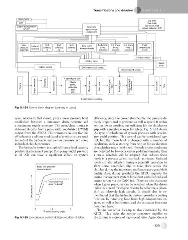
Fig. 5.1-24 Control block diagram (courtesy of Jatco).
open, relative to that closed, gives a mean pressure level efficiency, since the power absorbed by the pump is di-
established between a minimum drain pressure and rectly proportional to pressure, as well as speed. It is thus
a maximum supply pressure. The open/close timing is kept as low as possible, but sufficient for the clutches to
obtained directly from a pulse width modulated (PWM) grip with a suitable margin for safety. Fig. 5.1-25 shows
output from the ATCU. This transmission uses five on/ the type of scheduling of system pressure with acceler-
off solenoids and four modulated solenoids that are used ator pedal position. This control can be considered typ-
to control the hydraulic system line pressure and some ical, but the mean level is changed with a number of
individual clutch pressures. conditions, such as starting from rest; or for acceleration
The hydraulic system is supplied from a fixed capacity then a higher mean level is set. If steady cruise conditions
positive displacement pump. The pump outlet pressure are detected by low-accelerator pedal movements, then
in all ATs can have a significant effect on system a cruise schedule will be adopted that reduces these
levels in a process called ‘cut-back’ as shown. Reduced
levels are also adopted during a gearshift operation to
Basic line pressure allow some controlled slip to take place across the
characteristics clutches during the transition, and hence give a good shift
quality. Also, during gearshifts the ATCU requests the
engine management system for a short period of reduced
engine torque via the CAN link. There are also occasions
During driving
(After ‘cutback’) when higher pressures can be selected when the driver
Line pressure shift at relatively high speeds. It should also be re-
indicates a need for engine braking by selecting a down-
membered that the hydraulic system provides a cooling
function by removing heat from high-temperature re-
gions, as well as lubrication, and the actuation functions
described here.
0 1/2 1 Torque converter lock-up is also controlled by the
Throttle opening angle
ATCU. This locks the torque converter impeller to
Fig. 5.1-25 Line pressure control strategy (courtesy of Jatco). the turbine in regions of high-speed ratio. Again, there is
129