
Page 134 - Automotive Engineering Powertrain Chassis System and Vehicle Body
P. 134
CH AP TER 5 .1 Transmissions and driveline
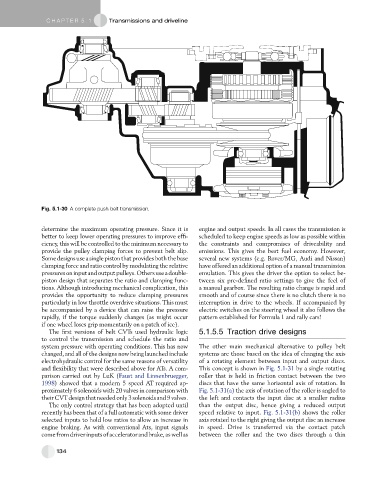
Fig. 5.1-30 A complete push belt transmission.
determine the maximum operating pressure. Since it is engine and output speeds. In all cases the transmission is
better to keep lower operating pressures to improve effi- scheduled to keep engine speeds as low as possible within
ciency, this will be controlled to the minimum necessary to the constraints and compromises of driveability and
provide the pulley clamping forces to prevent belt slip. emissions. This gives the best fuel economy. However,
Somedesignsuse asinglepistonthatprovidesboththebase several new systems (e.g. Rover/MG, Audi and Nissan)
clamping force and ratio control by modulating the relative have offered an additional option of a manual transmission
pressuresoninputandoutputpulleys.Othersuseadouble- emulation. This gives the driver the option to select be-
piston design that separates the ratio and clamping func- tween six pre-defined ratio settings to give the feel of
tions. Although introducing mechanical complication, this a manual gearbox. The resulting ratio change is rapid and
provides the opportunity to reduce clamping pressures smooth and of course since there is no clutch there is no
particularly in low throttle overdrive situations. This must interruption in drive to the wheels. If accompanied by
be accompanied by a device that can raise the pressure electric switches on the steering wheel it also follows the
rapidly, if the torque suddenly changes (as might occur pattern established for Formula 1 and rally cars!
if one wheel loses grip momentarily on a patch of ice).
The first versions of belt CVTs used hydraulic logic 5.1.5.5 Traction drive designs
to control the transmission and schedule the ratio and
system pressure with operating conditions. This has now The other main mechanical alternative to pulley belt
changed, and all of the designs now being launched include systems are those based on the idea of changing the axis
electrohydraulic control for the same reasons of versatility of a rotating element between input and output discs.
and flexibility that were described above for ATs. A com- This concept is shown in Fig. 5.1-31 by a single rotating
parison carried out by LuK (Faust and Linnenbruegger, roller that is held in friction contact between the two
1998) showed that a modern 5 speed AT required ap- discs that have the same horizontal axis of rotation. In
proximately 6 solenoids with 20 valves in comparison with Fig. 5.1-31(a) the axis of rotation of the roller is angled to
theirCVTdesignthatneededonly3solenoidsand9valves. the left and contacts the input disc at a smaller radius
The only control strategy that has been adopted until than the output disc, hence giving a reduced output
recently has been that of a full automatic with some driver speed relative to input. Fig. 5.1-31(b) shows the roller
selected inputs to hold low ratios to allow an increase in axis rotated to the right giving the output disc an increase
engine braking. As with conventional Ats, input signals in speed. Drive is transferred via the contact patch
come fromdriverinputs ofacceleratorandbrake,as wellas between the roller and the two discs through a thin
134