
Page 136 - Automotive Engineering Powertrain Chassis System and Vehicle Body
P. 136
CH AP TER 5 .1 Transmissions and driveline
under development for demonstration in sports utility Unfortunately it cannot then also meet the high
vehicles. This is also a dual cavity with three rollers in each, overdrive ratio that is necessary for good economy and
a front rear layout and rated for 5 Litre engines producing the range needs to be extended through what is called
around 450 Nm torque. In prototype form it has also been a mode change. In high regime the variator output is
fitted to the 2 Litre Ford Mondeo in a front-wheel-drive locked directly to the annulus and transmission output
configuration. This transmission is notable for the use shafts by a multi-plate clutch. At the same time the
of the split path principle to provide an IVTcharacteristic second clutch disconnects the transfer drive input to the
from a CVT variator. carrier of the epicyclic. The change between high and low
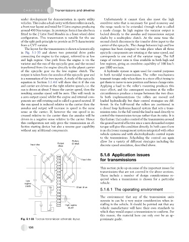
The layout for the transmission is shown schematically regimes has been designed to take place when all three
in Fig. 5.1-33 and shows two potential drive paths epicyclic components are rotating at the same speed, and
connecting the engine to the output, referred to as low corresponds to one end of the variator range. The full
and high regime. One path from the engine is via the range of variator ratio is thus available in both high and
variator and the sun of the epicyclic gear, and the second low regimes, giving an overdrive capability of 100 km/h
transferred from the engine directly to the planet carrier per 1000 rev/min.
of the epicyclic gear via the low regime clutch. The A hydraulic system is again used for control purposes
output is taken from the annulus of the epicyclic gear and in both toroidal transmissions. The roller mechanisms
is a summation of the two inputs. A study of the epicyclic transmit torque only when there is a steer effect trying to
equation in Section 5.1.4.6 will show that it if the sun get them to move to new position and hence change ratio.
and carrier are driven at the right relative speeds, i.e. the Applying a load to the roller’s mounting produces this
sun is driven at about 3 times the carrier speed, then the steer effect, and the consequent reactions at the roller
resulting annulus speed will be zero. This will result in circumference produce a torque between the two discs.
a zero output speed whilst the engine and internal com- In both implementations the rollers are moved and
ponents are still rotating and is called a geared neutral. If loaded hydraulically but their control strategies are dif-
the sun speed is reduced relative to the carrier then the ferent. In the half-toroid the rollers are positioned in
annulus and output will increase in speed in the same a closed loop hydromechanical system that sets a trans-
sense as the carrier. If, however the sun speed is in- mission ratio. In the full toroid the load is used directly to
creased relative to the carrier then the annulus will be control the transmission torque rather than its ratio. It is
driven in a negative sense relative to the carrier. Hence this feature that makes control of the transmission around
this configuration not only gives the transmission an ef- the geared neutral effective since a zero demanded output
fective starting device but also a reverse gear capability torque will give this condition directly. In both cases there
without any additional components. is an electronic management system integrated with other
vehicle systems and with electrohydraulic control inputs
to the transmissions. Scheduling the control can again
Rollers allow for a variety of different strategies including the
Output (6 total)
Input disc discrete speed emulation, described above.
discs
5.1.6 Application issues
Input disc for transmissions
This section picks up on some of the important issues for
transmissions that are not covered in the above sections.
These include a number of design considerations re-
quired when a transmission is chosen for a particular
Low
regime vehicle.
clutch
Chain drive
5.1.6.1 The operating environment
The environment that any of the transmission units
operate in can be a very major consideration when in-
stalling in the vehicle. It should be pointed out that any
High regime
clutch vehicle manufacturer will have their own standards to
which they would expect a transmission to conform. For
this reason, the material here can only ever be an ap-
Fig. 5.1-33 Torotrak transmission schematic layout. proximate guide.
136