
Page 133 - Automotive Engineering Powertrain Chassis System and Vehicle Body
P. 133
Transmissions and driveline CHAPTER 5.1
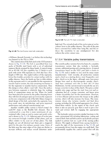
Fig. 5.1-29 The LuK-PIV chain construction.
high load. The extended ends of the rocker pins act as the
contact faces to the pulley sheaves. The ends of the pins
have a crowned face rather than being flat, and this re-
Fig. 5.1-28 The Van Doorne metal belt construction. duces the sensitivity to any misalignment but also
reduces the active contact area.
a Williams–Renault Formula 1 car before this technology
was banned by the FIA in 1994. 5.1.5.4 Variable pulley transmissions
The construction of the belt used in the VDTsystem is
shown in Fig. 5.1-28. The belt is assembled from two The variable pulley variators form the basis of a complete
packs of flexible steel bands with a set of individual transmission system that also includes a hydraulic
segment blocks retained by these bands. A typical design system, additional gearing and a starting device. A typical
for an 85 kW, 165 Nm capability has 12 bands in each transmission based on the VDT push belt is shown in
pack with about 430 segments in a belt that has a free Fig. 5.1-30, and is similar to that used by many major
length of 680 mm. The angled surface of the segments, manufacturers. Until recently, all production variants
below the shoulder, provides the contact surface with the used a clutch as a starting device, most frequently a wet
pulley sheaves. Since the bands are free to slide relative plate clutch as in the figure, although some low-power
to the segments and it is not possible for the segments to designs have used an electromagnetic powder clutch.
transfer load in tension, the only remaining mechanism is Audi have continued with this in their A6 2.4 Litre
for the segments to transfer load in compression. Thus Multitronic, but the current trend is towards the use of a
this design is often called a ‘push belt’. Since the surface torque converter in place of the clutch. This gives a wider
area between segments is relatively large the working useable ratio range and has the start from rest and ac-
levels of compression stress are low. When the bands celeration feel of a torque converter, and hence gives
have been placed in tension by the pulley clamping forces a better driveability feel for the transmission. However,
they will stretch and gaps open up between the segments it is less efficient and increases the torque in the pulley
on the non-compression side of the belt. Many changes in section, which will also increase the losses. The trans-
detail design of the belt, particularly the segments, have mission shown also includes transfer and final drive
been made since its introduction, and given improved gearing, including the differential appropriate for a front-
performance and reduced manufacturing cost. wheel-drive vehicle. In the region of the clutch pack
Another variable pulley system is based around the there is also an epicyclic gear that is used to give a for-
LuK-PIV chain as the flexible belt element. This is ward and reverse shift by engaging the appropriate
constructed in a way that is more reminiscent of con- clutch.
ventional roller chain as used in motor and pedal cycles The hydraulic system provides similar functions to the
and is shown in Fig. 5.1-29. Adjacent pairs of rocker pins more conventional ATs including lubrication, cooling and
are connected through a number of link plates, each set control. Both chain and belt systems use hydraulic pressure
offset relative to the next set of link plates. The link applied to pistons that are a part of the moving pulley
lengths are not all identical and these give a staggered sheaves. The supply is obtained from a pump, located to-
pitch for the pins that reduces acoustic noise. Some of wards the right of the transmission in Fig. 5.1-30,and
the links near the outer edges of the chain are thicker to permanently driven from the engine via a quill shaft. This
increase stiffness and reduce overall distortion under preferentially supplies the control system that will also
133