
Page 26 - Automotive Engineering Powertrain Chassis System and Vehicle Body
P. 26
CH AP TER 2 .1 Measurement of torque, power, speed and fuel consumption
trivial with modern computer control systems, but
there are also important problems that may reduce the
inherent accuracy of this arrangement.
T For steady state testing, a well-designed and main-
tained trunnion machine will give more consistently
R
auditable and accurate torque measurements than the
inline systems; the justification for this statement can be
F
listed as follows:
The in-line torque sensor has to be oversized for the
Carcase rating of its dynamometer and being oversized the
resolution of the signal is lower. The transducer has
to be overrated because it has to be capable of dealing
with the instantaneous torque peaks of the engine
Fixed which are not experienced by the load cell of a
base trunnion-bearing machine.
The transducer forms part of the drive line and
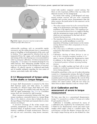
Fig. 2.1-2 Diagram of trunnion-mounted dynamometer requires very careful installation to avoid the
measuring torque with a load cell. imposition of bending or axial stresses on the torsion
sensing element from other components or its own
clamping device.
unfavourable conditions, with no perceptible angular The in-line device is difficult to protect from
movement, and the rolling element type is consequently temperature fluctuations within and around the
prone to brinelling, or local indentation of the races, and drive line.
to fretting. This is aggravated by vibration that may be Calibration checking of these devices is not as
transmitted from the engine and periodical inspection easy as for a trunnion-mounted machine; it re-
and turning of the outer bearing race is recommended in quires a means of locking the dynamometer shaft
order to avoid poor calibration. A Schenck dynamometer in addition to the fixing of a calibration arm in
design (Fig. 2.1-3) replaces the trunnion bearings by two a horizontal position without imposing bending
radial flexures, thus eliminating possible friction and stresses.
wear, but at the expense of the introduction of torsional Unlike the cradled machine and load cell, it is not
stiffness, of reduced capacity to withstand axial loads possible to verify the measured torque of an in-line
and of possible ambiguity regarding the true centre of device during operation.
rotation, particularly under side loading.
It should be noted that, in the case of modern alternating
current (a.c.) dynamometer systems, the tasks of torque
measurement and torque control may use different data
2.1.3 Measurement of torque using acquisition paths. In some installations the control of the
in-line shafts or torque flanges trunnion-mounted machine may use its own torque cal-
culation and control system, while the test values are
A torque shaft dynamometer is mounted in the drive taken from an inline transducer such as a torque shaft.
shaft between engine and brake device. It consists
essentially of a flanged torque shaft fitted with strain 2.1.4 Calibration and the
gauges and designs are available both with slip rings and assessment of errors in torque
with RF signal transmission. Fig. 2.1-4 is a brushless
torque shaft unit intended for rigid mounting. measurement
More common in automotive testing is the ‘disc’ type
torque transducer, commonly known as a torque flange We have seen that in a conventional dynamometer,
(Fig. 2.1-5), which is a device that is bolted directly to torque T is measured as a product of torque arm radius
the input flange of the brake and transmits data to a static R and transducer force F.
antenna encircling it. Calibration is invariably performed by means of
A perceived advantage of the in-line torque mea- a calibration arm, supplied by the manufacturer, which
surement arrangement is that it avoids the necessity, is bolted to the dynamometer carcase and carries dead
discussed below, of applying torque corrections under weights which apply a load at a certified radius. The
transient conditions of torque measurement. However, manufacturer certifies the distance between the axis of
not only are such corrections, using known constants, the weight hanger bearing and an axis defined by a line
22