
Page 31 - Automotive Engineering Powertrain Chassis System and Vehicle Body
P. 31
Measurement of torque, power, speed and fuel consumption CHAPTER 2.1
2.1.7 Choice of dynamometer A shaft carries a cylindrical rotor which revolves in
a watertight casing. Toroidal recesses formed half in the
rotor and half in the casing or stator are divided into
Perhaps the most difficult question facing the engineer
setting up a test facility is the choice of the most suitable pockets by radial vanes set at an angle to the axis of the
dynamometer. In this part of the chapter the character- rotor. When the rotor is driven, centrifugal force sets up
istics, advantages and disadvantages of the various types an intensive toroidal circulation as indicated by the
are discussed and a procedure for arriving at the correct arrows in Fig. 2.1-9a. The effect is to transfer momentum
choice is described. from rotor to stator and hence to develop a torque re-
The earliest form of dynamometer, the rope brake sistant to the rotation of the shaft, balanced by an equal
dates back to the early years of the last century. An ex- and opposite torque reaction on the casing.
tremely dangerous device, it was nevertheless capable of A forced vortex of toroidal form is generated as
giving quite accurate measurements of power. Its succes- a consequence of this motion, leading to high rates of
sor, the Prony brake, also relied on mechanical friction and turbulent shear in the water and the dissipation of power
like the rope brake required cooling by water introduced in the form of heat to the water. The centre of the vortex
into the hollow brake drum and removed by a scoop. is vented to atmosphere by way of passages in the rotor
Both these devices are only of historical interest. Their and the virtue of the design is that power is absorbed
successors may be classified according to the means with minimal damage to the moving surfaces, either from
adopted for absorbing the mechanical power of the prime erosion or from the effects of cavitation.
mover driving the dynamometer. The machines are of two kinds, depending on the
means by which the resisting torque is varied.
1(a) Constant fill machines: the classical Froude or
2.1.8 Classification sluice plate design, Fig. 2.1-10. In this machine, torque is
of dynamometers varied by inserting or withdrawing pairs of thin sluice
plates between rotor and stator, thus controlling the
extent of the development of the toroidal vortices.
1. Hydrokinetic or ‘hydraulic’ dynamometers (water 1(b) Variable fill machines, Fig. 2.1-11. In these
brakes). With the exception of the disc dynamometer, machines, the torque absorbed is varied by adjusting the
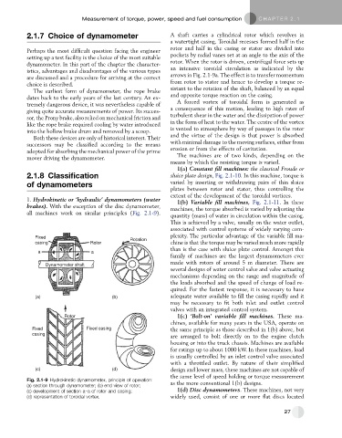
all machines work on similar principles (Fig. 2.1-9).
quantity (mass) of water in circulation within the casing.
This is achieved by a valve, usually on the water outlet,
associated with control systems of widely varying com-
Fixed Rotation plexity. The particular advantage of the variable fill ma-
casing Rotor chine is that the torque may be varied much more rapidly
than is the case with sluice plate control. Amongst this
a a
family of machines are the largest dynamometers ever
made with rotors of around 5 m diameter. There are
Dynamometer shaft
several designs of water control valve and valve actuating
mechanisms depending on the range and magnitude of
the loads absorbed and the speed of change of load re-
quired. For the fastest response, it is necessary to have
(a) (b) adequate water available to fill the casing rapidly and it
may be necessary to fit both inlet and outlet control
valves with an integrated control system.
Rotor 1(c) ‘Bolt-on’ variable fill machines. These ma-
chines, available for many years in the USA, operate on
Fixed Fixed casing the same principle as those described in 1(b) above, but
casing
are arranged to bolt directly on to the engine clutch
housing or into the truck chassis. Machines are available
for ratings up to about 1000 kW. In these machines, load
is usually controlled by an inlet control valve associated
with a throttled outlet. By nature of their simplified
(c) (d) design and lower mass, these machines are not capable of
the same level of speed holding or torque measurement
Fig. 2.1-9 Hydrokinetic dynamometer, principle of operation:
(a) section through dynamometer; (b) end view of rotor; as the more conventional 1(b) designs.
(c) development of section a–a of rotor and casing; 1(d) Disc dynamometers. These machines, not very
(d) representation of toroidal vortex. widely used, consist of one or more flat discs located
27