
Page 29 - Automotive Engineering Powertrain Chassis System and Vehicle Body
P. 29
Measurement of torque, power, speed and fuel consumption CHAPTER 2.1
1.000 0.250
0.800 0.200
0.600 0.150
0.400 0.100
0.200 0.050
% Error –0.200 0.000 100.000 200.000 300.000 400.000 500.000 600.000 700.000 % Error –0.050 0.000 100.000 200.000 300.000 400.000 500.000 600.000 700.000
0.000
0.000
–0.400 –0.100
–0.600 –0.150
–0.800 –0.200
–1.000 –1.250
Applied torque Nm Applied torque
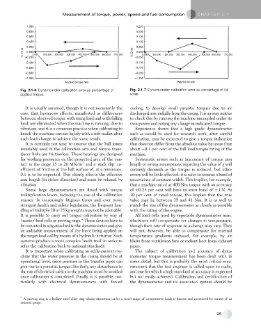
Fig. 2.1-6 Dynamometer calibration error as percentage of Fig. 2.1-7 Dynamometer calibration error as percentage of full
applied torque. scale.
It is usually assumed, though it is not necessarily the cooling, to develop small parasitic torques due to air
case, that hysteresis effects, manifested as differences discharged non-radially from the casing. It is an easy matter
between observed torque with rising load and with falling to check this by running the machine uncoupled under its
load, are eliminated when the machine is running, due to own power and noting any change in indicated torque.
vibration, and it is a common practice when calibrating to Experience shows that a high grade dynamometer
knock the machine carcase lightly with a soft mallet after such as would be used for research work, after careful
each load change to achieve the same result. calibration, may be expected to give a torque indication
It is certainly not wise to assume that the ball joints that does not differ from the absolute value by more than
invariably used in the calibration arm and torque trans- about 0.1 per cent of the full load torque rating of the
ducer links are frictionless. These bearings are designed machine.
for working pressures on the projected area of the con- Systematic errors such as inaccuracy of torque arm
2
tact in the range 15 to 20 MN/m and a ‘stick slip’ co- length or wrong assumptions regarding the value of g will
efficient of friction at the ball surface of, at a minimum, certainly diminish as the torque is reduced, but other
0.1 is to be expected. This clearly affects the effective errors will be little affected: it is safer to assume a band of
arm length (in either direction) and must be relaxed by uncertainty of constant width. This implies, for example,
vibration. that a machine rated at 400 Nm torque with an accuracy
Some large dynamometers are fitted with torque of 0.25 per cent will have an error band of 1N. At
multiplication levers, reducing the size of the calibration 10 per cent of rated torque, this implies that the true
masses. In increasingly litigious times and ever more value may lie between 39 and 41 Nm. It is as well to
stringent health and safety legislation, the frequent han- match the size of the dynamometer as closely as possible
dling of multiple 20 or 25 kg weights may not be advisable. with the rating of the engine.
It is possible to carry out torque calibration by way of All load cells used by reputable dynamometer man-
‘master’ load cells or proving rings.* These devices have to ufacturers will compensate for changes in temperature,
be mounted in a jig attached to the dynamometer and give though their rate of response to a change may vary. They
an auditable measurement of the force being applied on will not, however, be able to compensate for internal
the target load cell by means of a hydraulic actuator. Such temperature gradients induced, for example, by air
systems produce a more complex ‘audit trail’ in order to blasts from ventilation fans or radiant heat from exhaust
refer the calibration back to national standards. pipes.
It is important when calibrating an eddy-current ma- The subject of calibration and accuracy of dyna-
chine that the water pressure in the casing should be at mometer torque measurement has been dealt with in
operational level, since pressure in the transfer pipes can some detail, but this is probably the most critical mea-
give rise to a parasitic torque. Similarly, any disturbance to surement that the test engineer is called upon to make,
the run of electrical cables to the machine must be avoided and one for which a high standard of accuracy is expected
once calibration is completed. Finally, it is possible, par- but not easily achieved. Calibration and certification of
ticularly with electrical dynamometers with forced the dynamometer and its associated system should be
* A proving ring is a hollow steel alloy ring whose distortion under a rated range of compressive loads is known and measured by means of an
internal gauge.
25