
Page 34 - Automotive Engineering Powertrain Chassis System and Vehicle Body
P. 34
CH AP TER 2 .1 Measurement of torque, power, speed and fuel consumption
clearance, between water-cooled steel loss plates. A mag- Although no longer so widely used, an alternative form of
netic field parallel to the machine axis is generated by two eddy-current machine is also available. This employs
annular coils and motion ofthe rotorgivesrise to changesin a simple disc or drum design of rotor in which eddy
the distribution of magnetic flux in the loss plates. This in currents are induced and the heat developed is trans-
turn gives rise to circulating eddy currents and the dissi- ferred to water circulated through the gaps between
pation of power in the form of electrical resistive losses. rotor and stator. These ‘wet gap’ machines are liable to
Energy is transferred in the form of heat to cooling water corrosion if left static for any length of time, have higher
circulating through passages in the loss plates, while some inertia, and have a high level of minimum torque, arising
cooling is achieved by the radial flow of air in the gaps be- from drag of the cooling water in the gap.
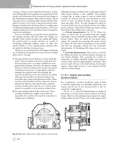
tween rotor and plates. 4. Friction dynamometers, Fig. 2.1-12. These ma-
Power is controlled by varying the current supplied to chines, in direct line of succession from the original
the annular exciting coils and rapid load changes are rope brake, consist essentially of water-cooled, multidisc
possible. Eddy-current machines are simple and robust, friction brakes. They are useful for low-speed appli-
the control system is simple and they are capable of cations, for example for measuring the power output
developing substantial braking torque at quite low of a large, off-road vehicle transmission at the wheels,
speeds. Unlike a.c. or d.c. dynamometers, however, they and have the advantage, shared with the hydrostatic
are unable to develop motoring torque. dynamometer, of developing full torque down to zero
There are two common forms of machine both having speed.
air circulating in the gap between rotor and loss (cooling) 5. Air brake dynamometers. These devices, of which
plates, hence ‘dry gap’: the Walker fan brake was the best-known example, are
now largely obsolete. They consisted of a simple ar-
1. Dry gap machines fitted with one or more tooth disc rangement of radially adjustable paddles that imposed
rotors. These machines have lower inertia than the a torque that could be approximately estimated. They
drum machines and a very large installed user base, survive mainly for use in the field testing of helicopter
particularly in Europe. However, the inherent design engines, where high accuracy is not required and the
features of their loss plates place certain operational noise is no disadvantage.
restrictions on their use. It is absolutely critical to
maintain the required water flow through the
machines at all times; even a very short loss of cooling 2.1.8.1 Hybrid and tandem
will cause the loss plates to distort leading to the dynamometers
rotor/plate gap closing with disastrous results. These
machines must be fitted with flow detection devices For completeness, mention should be made of both
interlocked with the cell control system; pressure a combined design that is occasionally adopted for cost
switches should not be used since in a closed water reasons and the use of two dynamometers in line for
system it is possible to have pressure without flow.
special test configurations.
2. Dry gap machines fitted with a drum rotor. These The d.c. or a.c. electrical dynamometer is capable of
machines usually have a higher inertia than the generating a motoring torque almost equal to its braking
equivalent disc machine, but may be less sensitive to torque. However, the motoring torque required in engine
cooling water conditions. testing seldom exceeds 30 per cent of the engine power
Fig. 2.1-12 Water-cooled friction brake used as a dynamometer.
30