
Page 35 - Automotive Engineering Powertrain Chassis System and Vehicle Body
P. 35
Measurement of torque, power, speed and fuel consumption CHAPTER 2.1
output. Since, for equal power absorption, a.c. and d.c.
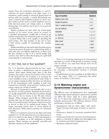
Table 2.1-2 Operating quadrants of dynamometer designs
machines are more expensive than other types, it is
sometimes worth running an electrical dynamometer in Type of machine Quadrant
tandem with, for example, a variable fill hydraulic ma-
chine. Control of these hybrid machines is a more com- Hydraulic sluice plate 1 or 2
plex matter and the need to provide duplicate services, Variable fill hydraulic 1 or 2
both electrical power and cooling water, is a further
disadvantage. The solution may, however, on occasion be ‘Bolt on’ variable fill hydraulic 1 or 2
cost-effective. Disc type hydraulic 1 and 2
Tandem machines are used when the torque/speed
envelope of the prime mover cannot be covered by Hydrostatic 1, 2, 3, 4
a standard dynamometer, usually this is found in gas d.c. electrical 1, 2, 3, 4
turbine testing when the rotational speed is too high for
a machine fitted with a rotor capable of absorbing full a.c. electrical 1, 2, 3, 4
rated torque. The first machine in line has to have Eddy current 1 and 2
a shaft system capable of transmitting the combine
torques. Friction brake 1 and 2
Tandem machines are also used when the prime mover Air brake 1 and 2
is producing power through two contrarotating shafts as
with some aero and military applications; in these cases Hybrid 1, 2, 3, 4
the first machine in line is of a special design with
a hollow rotor shaft to allow the housing of a quill shaft
connecting the second machine.
There is an increasing requirement for four-quadrant
operation as a result of the growth in transient testing,
2.1.8.2 One, two or four quadrant? with its call for very rapid load changes and even for
torque reversals.
Fig. 2.1-8 illustrates diagrammatically the four ‘quad- If mechanical losses in the engine are to be measured
rants’ in which a dynamometer may be required to by ‘motoring’, a four-quadrant machine is obviously
operate. Most engine testing takes place in the first required.
quadrant, the engine running anticlockwise when viewed A useful feature of such a machine is its ability also to
on the flywheel end. On occasions it is necessary for start the engine. Table 2.1-2 summarizes the perfor-
a test installation using a unidirectional water brake to mance of machines in this respect.
accept engines running in either direction; one solution is
to fit the dynamometer with couplings at both ends
mounted on a turntable. Large and some ‘medium speed’ 2.1.9 Matching engine and
marine engines are usually reversible. dynamometer characteristics
All types of dynamometer are naturally able to run in
the first (or second) quadrant. Hydraulic dynamometers The different types of dynamometer have significantly
are usually designed for one direction of rotation, though different torque-speed and power–speed curves, and this
they may be run in reverse at low fill state without can affect the choice made for a given application.
damage. When designed specifically for bidirectional Fig. 2.1-13 shows the performance curves of a typical
rotation they may be larger than a single-direction ma- hydraulic dynamometer. The different elements of the
chine of equivalent power and torque control may not be performance envelope are as follows:
as precise as that of the unidirectional designs. The
torque measuring system must of course operate in Dynamometer full (or sluice plates wide open).
both directions. Eddy-current machines are inherently Torque increases with square of speed, no torque at
reversible. rest.
When it is required to operate in the third and fourth Performance limited by maximum permitted shaft
quadrants (i.e. for the dynamometer to produce power as torque.
well as to absorb it) the choice is effectively limited to Performance limited by maximum permitted power,
d.c. or a.c. machines, or to the hydrostatic or hybrid which is a function of cooling water throughput and
machine. These machines are generally reversible and its maximum permitted temperature rise.
therefore operate in all four quadrants. Maximum permitted speed.
31