
Page 33 - Automotive Engineering Powertrain Chassis System and Vehicle Body
P. 33
Measurement of torque, power, speed and fuel consumption CHAPTER 2.1
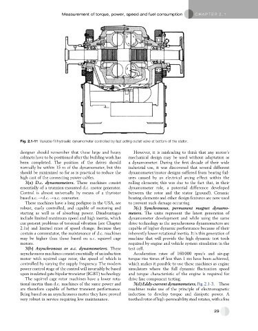
Fig. 2.1-11 Variable fill hydraulic dynamometer controlled by fast acting outlet valve at bottom of the stator.
designer should remember that these large and heavy However, it is misleading to think that any motor’s
cabinets have to be positioned after the building work has mechanical design may be used without adaptation as
been completed. The position of the drives should a dynamometer. During the first decade of their wide
normally be within 15 m of the dynamometer, but this industrial use, it was discovered that several different
should be minimized so far as is practical to reduce the dynamometer/motor designs suffered from bearing fail-
high cost of the connecting power cables. ures caused by an electrical arcing effect within the
3(a) D.c. dynamometers. These machines consist rolling elements; this was due to the fact that, in their
essentially of a trunnion-mounted d.c. motor generator. dynamometer role, a potential difference developed
Control is almost universally by means of a thyristor between the rotor and the stator (ground). Ceramic
based a.c./d.c./a.c. converter. bearing elements and other design features are now used
These machines have a long pedigree in the USA, are to prevent such damage occurring.
robust, easily controlled, and capable of motoring and 3(c) Synchronous, permanent magnet dynamo-
starting as well as of absorbing power. Disadvantages meters. The units represent the latest generation of
include limited maximum speed and high inertia, which dynamometer development and while using the same
can present problems of torsional vibration (see Chapter drive technology as the asynchronous dynamometers are
2.1a) and limited rates of speed change. Because they capable of higher dynamic performance because of their
contain a commutator, the maintenance of d.c. machines inherently lower rotational inertia. It is this generation of
may be higher than those based on a.c. squirrel cage machine that will provide the high dynamic test tools
motors. required by engine and vehicle system simulation in the
3(b) Asynchronous or a.c. dynamometers. These test cell.
asynchronous machines consist essentially of an induction Acceleration rates of 160 000 rpm/s and air-gap
motor with squirrel cage rotor, the speed of which is torque rise times of less than 1 ms have been achieved,
controlled by varying the supply frequency. The modern which makes it possible to use these machines as engine
power control stage of the control will invariably be based simulators where the full dynamic fluctuation speed
upon insulated gate bipolar transistor (IGBT) technology. and torque characteristic of the engine is required for
The squirrel cage rotor machines have a lower rota- drive line component testing.
tional inertia than d.c. machines of the same power and 3(d)Eddy-currentdynamometers,Fig.2.1-3. These
are therefore capable of better transient performance. machines make use of the principle of electromagnetic
Being based on an asynchronous motor they have proved induction to develop torque and dissipate power. A
very robust in service requiring low maintenance. toothed rotor of high-permeability steelrotates, with a fine
29