
Page 408 - Automotive Engineering Powertrain Chassis System and Vehicle Body
P. 408
Vehicle motion control C HAPTER 13.1
iron particles begin to align with the field, and the In conjunction with a suitable control system, the
viscosity increases in proportion to the strength of pneumatic springs can automatically adjust the vehicle
the field (which is proportional to the current through the height to accommodate various vehicle loadings.
electromagnet coil). That is, the damping of the associ-
ated shock absorber/strut varies continuously with the 13.1.5.3 Electronic suspension control
electromagnet coil current.
system
13.1.5.2 Variable spring rate The control system for a typical electronic suspension
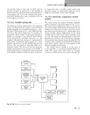
system is depicted in the block diagram of Fig. 13.1-22.
The frequency response characteristics of a suspension The control system configuration in Fig. 13.1-22 is generic
system are influenced by the springs as well as the shock and not necessarily representative of the system for any
absorber damping. Conventional steel springs (i.e., coil or production car. This system includes sensors for measur-
leaf) have a fixed spring rate (i.e., force-deflection char- ing vehicle speed; steering input (i.e., angular deflection of
acteristics). The vehicle height above the ground is de- steered wheels); relative displacement of the wheel
termined by vehicle weight, which in turn depends on assembly and car body/chassis; lateral acceleration; and
loading (i.e., passengers, cargo, and fuel). Some vehicles, yaw rate. The outputs are electrical signals to the shock
having electronically controlled suspension, are also absorber/strut actuators and to the motor/compressor
equipped with pneumatic springs as a replacement for that pressurizes the pneumatic springs (if applicable). The
steel springs. A pneumatic spring consists of a rubber actuators can be solenoid-operated (switched) orifices or
bladder mounted in an assembly and filled with air under motor-driven variable orifices or electromagnets for RH
pressure. This mechanism is commonly called an air fluid-type variable viscosity struts.
suspension system. The spring rate for such pneumatic The control system typically is in the form of
springs is proportional to the pressure in the bladder. A a microcontroller or microprocessor-based digital con-
motor-driven pump is provided that varies the pressure troller. The inputs from each sensor are sampled,
in the bladder, yielding a variable spring rate suspension. converted to digital format, and stored in memory. The
Fig. 13.1-22 Electronic suspension system.
413