
Page 403 - Automotive Engineering Powertrain Chassis System and Vehicle Body
P. 403
CHAP TER 1 3. 1 Vehicle motion control
Fig. 13.1-16 Brake pressure modulating mechanism.
brake line pressure. The ABS system will continue to to its normal position (fully up) such that the check valve
cycle until the vehicle has stopped, the braking condi- is held open.
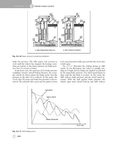
tions are normal, or the driver removes the brake pres- Fig. 13.1-17 illustrates the braking during an ABS
sure from the master cylinder. action. In this illustration, the vehicle is initially trav-
In the latter case, the operation of the brake pressure eling at 55 mph and the brakes are applied as indicated
modulator restores normal braking function. For exam- by the rising brake pressure. The wheel speed begins to
ple, should the driver release the brake pedal, then the drop until the slip limit is reached. At this point, the
pressure at the inlet (1) is reduced. At this point, the ABS reduces brake pressure and the wheel speed in-
check valve (9) opens and brake line pressure is also re- creases. With the high applied brake pressure, the
moved. The solenoid valve opens and the piston returns wheels again tend toward lock-up and ABS reduces
Fig. 13.1-17 ABS braking action.
408