
Page 400 - Automotive Engineering Powertrain Chassis System and Vehicle Body
P. 400
Vehicle motion control C HAPTER 13.1
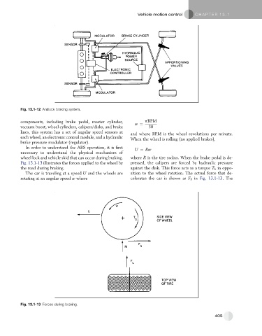
Fig. 13.1-12 Antilock braking system.
components, including brake pedal, master cylinder, w ¼ pRPM
vacuum boost, wheel cylinders, calipers/disks, and brake 30
lines, this system has a set of angular speed sensors at and where RPM is the wheel revolutions per minute.
each wheel, an electronic control module, and a hydraulic When the wheel is rolling (no applied brakes),
brake pressure modulator (regulator).
In order to understand the ABS operation, it is first U ¼ Rw
necessary to understand the physical mechanism of
wheel lock and vehicle skid that can occur during braking. where R is the tire radius. When the brake pedal is de-
Fig. 13.1-13 illustrates the forces applied to the wheel by pressed, the calipers are forced by hydraulic pressure
the road during braking. against the disk. This force acts as a torque T b in oppo-
The car is traveling at a speed U and the wheels are sition to the wheel rotation. The actual force that de-
rotating at an angular speed w where celerates the car is shown as F b in Fig. 13.1-13. The
Fig. 13.1-13 Forces during braking.
405