
Page 395 - Automotive Engineering Powertrain Chassis System and Vehicle Body
P. 395
CHAP TER 1 3. 1 Vehicle motion control
ROM RAM
AB
VEHICLE I/O DB MICROPROCESSOR–
SPEED
SENSOR INTERFACE BASED CONTROLLER
CB
DRIVER
CIRCUIT THROTTLE
FOR ACTUATOR
ACTUATOR
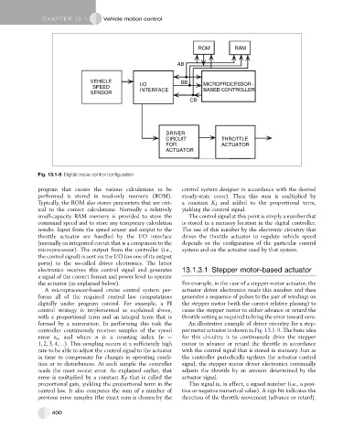
Fig. 13.1-8 Digital cruise control configuration.
program that causes the various calculations to be control system designer in accordance with the desired
performed is stored in read-only memory (ROM). steady-state error). Then this sum is multiplied by
Typically, the ROM also stores parameters that are crit- a constant K I and added to the proportional term,
ical to the correct calculations. Normally a relatively yielding the control signal.
small-capacity RAM memory is provided to store the The control signal at this point is simply a number that
command speed and to store any temporary calculation is stored in a memory location in the digital controller.
results. Input from the speed sensor and output to the The use of this number by the electronic circuitry that
throttle actuator are handled by the I/O interface drives the throttle actuator to regulate vehicle speed
(normally an integrated circuit that is a companion to the depends on the configuration of the particular control
microprocessor). The output from the controller (i.e., system and on the actuator used by that system.
the control signal) is sent via the I/O (on one of its output
ports) to the so-called driver electronics. The latter
electronics receives this control signal and generates 13.1.3.1 Stepper motor-based actuator
a signal of the correct format and power level to operate
the actuator (as explained below). For example, in the case of a stepper motor actuator, the
A microprocessor-based cruise control system per- actuator driver electronics reads this number and then
forms all of the required control law computations generates a sequence of pulses to the pair of windings on
digitally under program control. For example, a PI the stepper motor (with the correct relative phasing) to
control strategy is implemented as explained above, cause the stepper motor to either advance or retard the
with a proportional term and an integral term that is throttle setting as required to bring the error toward zero.
formed by a summation. In performing this task the An illustrative example of driver circuitry for a step-
controller continuously receives samples of the speed per motor actuator is shown in Fig. 13.1-9. The basic idea
error e n , and where n is a counting index (n ¼ for this circuitry is to continuously drive the stepper
1, 2, 3, 4,.). This sampling occurs at a sufficiently high motor to advance or retard the throttle in accordance
rate to be able to adjust the control signal to the actuator with the control signal that is stored in memory. Just as
in time to compensate for changes in operating condi- the controller periodically updates the actuator control
tion or to disturbances. At each sample the controller signal, the stepper motor driver electronics continually
reads the most recent error. As explained earlier, that adjusts the throttle by an amount determined by the
error is multiplied by a constant K P that is called the actuator signal.
proportional gain, yielding the proportional term in the This signal is, in effect, a signed number (i.e., a posi-
control law. It also computes the sum of a number of tive or negative numerical value). A sign bit indicates the
previous error samples (the exact sum is chosen by the direction of the throttle movement (advance or retard).
400