
Page 399 - Automotive Engineering Powertrain Chassis System and Vehicle Body
P. 399
CHAP TER 1 3. 1 Vehicle motion control
VACUUM
BOOST
BRAKE ISOLATION
PEDAL VALVE
MASTER B
CYLINDER
A
MOTOR WHEEL
APPLY CYLINDER
VALVE
PUMP
CV 1
SET I
M RELEASE
WHEEL CV 2
SPEED ACC VALVE
CONTROLLER A
SENSOR ACCUM
R
BRAKE
PRESSURE
SENSOR THROTTLE
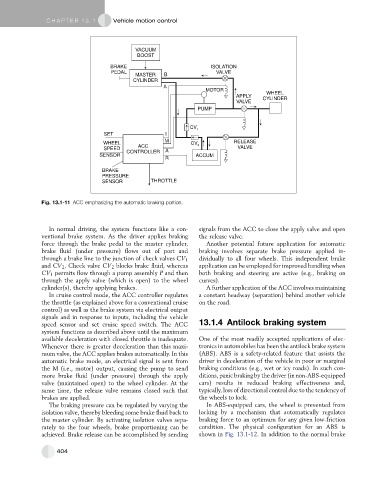
Fig. 13.1-11 ACC emphasizing the automatic braking portion.
In normal driving, the system functions like a con- signals from the ACC to close the apply valve and open
ventional brake system. As the driver applies braking the release valve.
force through the brake pedal to the master cylinder, Another potential future application for automatic
brake fluid (under pressure) flows out of port and braking involves separate brake pressure applied in-
through a brake line to the junction of check valves CV 1 dividually to all four wheels. This independent brake
and CV 2 . Check valve CV 2 blocks brake fluid, whereas application can be employed for improved handling when
CV 1 permits flow through a pump assembly P and then both braking and steering are active (e.g., braking on
through the apply valve (which is open) to the wheel curves).
cylinder(s), thereby applying brakes. A further application of the ACC involves maintaining
In cruise control mode, the ACC controller regulates a constant headway (separation) behind another vehicle
the throttle (as explained above for a conventional cruise on the road.
control) as well as the brake system via electrical output
signals and in response to inputs, including the vehicle
speed sensor and set cruise speed switch. The ACC 13.1.4 Antilock braking system
system functions as described above until the maximum
available deceleration with closed throttle is inadequate. One of the most readily accepted applications of elec-
Whenever there is greater deceleration than this maxi- tronics in automobiles has been the antilock brake system
mum valve, the ACC applies brakes automatically. In this (ABS). ABS is a safety-related feature that assists the
automatic brake mode, an electrical signal is sent from driver in deceleration of the vehicle in poor or marginal
the M (i.e., motor) output, causing the pump to send braking conditions (e.g., wet or icy roads). In such con-
more brake fluid (under pressure) through the apply ditions, panic braking by the driver (in non-ABS-equipped
valve (maintained open) to the wheel cylinder. At the cars) results in reduced braking effectiveness and,
same time, the release valve remains closed such that typically, loss of directional control due to the tendency of
brakes are applied. the wheels to lock.
The braking pressure can be regulated by varying the In ABS-equipped cars, the wheel is prevented from
isolation valve, thereby bleeding some brake fluid back to locking by a mechanism that automatically regulates
the master cylinder. By activating isolation valves sepa- braking force to an optimum for any given low-friction
rately to the four wheels, brake proportioning can be condition. The physical configuration for an ABS is
achieved. Brake release can be accomplished by sending shown in Fig. 13.1-12. In addition to the normal brake
404