
Page 402 - Automotive Engineering Powertrain Chassis System and Vehicle Body
P. 402
Vehicle motion control C HAPTER 13.1
braking torque and wheel deceleration by the following 4. EMB braking action
equation: 5. DC motor pack
T w ¼ T þ I w _ w 6. ESB braking
b
where I w is the wheel moment of inertia and _ w is 7. Gear assembly
the wheel deceleration (dw/dt, i.e., the rate of change of 8. Ball screw
wheel speed). 9. Check valve unseated
During heavy braking under marginal conditions, suf-
ficient braking force is applied to cause wheel lock-up (in 10. Outlet to brake cylinders
the absence of ABS control). We assume such heavy 11. Piston
braking for the following discussion of the ABS. As brake
pressure is applied, T b increases and w decreases, causing The numbers in Fig. 13.1-16b refer to the following:
slip to increase. The wheel torque is proportional to m b , 1. Trapped bypass brake fluid
which reaches a peak at slip S o . Consequently, the wheel 2. Solenoid valve activated
torque reaches a maximum value (assuming sufficient 3. EMB action released
brake force is applied) at this level of slip.
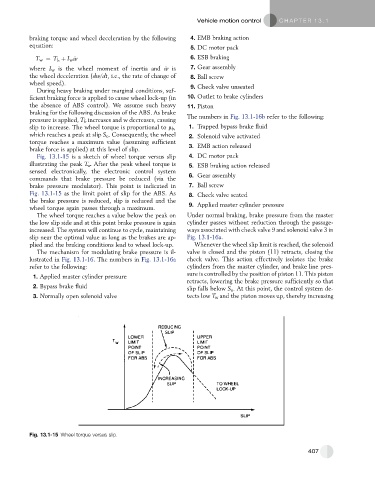
Fig. 13.1-15 is a sketch of wheel torque versus slip 4. DC motor pack
illustrating the peak T w . After the peak wheel torque is 5. ESB braking action released
sensed electronically, the electronic control system 6. Gear assembly
commands that brake pressure be reduced (via the
brake pressure modulator). This point is indicated in 7. Ball screw
Fig. 13.1-15 as the limit point of slip for the ABS. As 8. Check valve seated
the brake pressure is reduced, slip is reduced and the
wheel torque again passes through a maximum. 9. Applied master cylinder pressure
The wheel torque reaches a value below the peak on Under normal braking, brake pressure from the master
the low slip side and at this point brake pressure is again cylinder passes without reduction through the passage-
increased. The system will continue to cycle, maintaining ways associated with check valve 9 and solenoid valve 3 in
slip near the optimal value as long as the brakes are ap- Fig. 13.1-16a.
plied and the braking conditions lead to wheel lock-up. Whenever the wheel slip limit is reached, the solenoid
The mechanism for modulating brake pressure is il- valve is closed and the piston (11) retracts, closing the
lustrated in Fig. 13.1-16. The numbers in Fig. 13.1-16a check valve. This action effectively isolates the brake
refer to the following: cylinders from the master cylinder, and brake line pres-
sure is controlled by the position of piston 11. This piston
1. Applied master cylinder pressure
retracts, lowering the brake pressure sufficiently so that
2. Bypass brake fluid slip falls below S o . At this point, the control system de-
3. Normally open solenoid valve tects low T w and the piston moves up, thereby increasing
Fig. 13.1-15 Wheel torque versus slip.
407