
Page 406 - Automotive Engineering Powertrain Chassis System and Vehicle Body
P. 406
Vehicle motion control C HAPTER 13.1
to be varied electrically, which in turn permits the ride/
Region Frequency (Hz) Damping
handling characteristics to be varied while the car is in
1: Sprung mass mode 1–2 High motion. Under normal steady-cruise conditions, damping
is electrically set low, yielding a good ride. However,
2: Intermediate ride 2–8 Low
under dynamic maneuvering conditions (e.g., cornering),
3: Unsprung mass resonance 8–20 High the damping is set high to yield good handling. Generally
speaking, high damping reduces vehicle roll in response
4: Harshness >20 Low
to cornering or turning maneuvers, and it tends to
maintain tire force on the road for increased cornering
forces. Variable damping suspension systems can improve
Car handling generally improves if the amount of roll safety, particularly for vehicles with a relatively high
for any given maneuver is reduced. The rolling rate for center of gravity (e.g., SUVs).
a given car and maneuver is improved if spring rate and The damping of a suspension system is determined by
shock absorber damping are increased. Although the the viscosity of the fluid in the shock absorber/strut and
semiactive control system regulates only the damping, by the size of the aperture through which the fluid flows
handling is improved by increasing this damping as lateral as the wheel moves relative to the car body.
acceleration increases. The earliest active or semiactive suspension systems
Lateral acceleration A L is proportional to vehicle employed variable aperture. One scheme for achieving
speed and input steering angle: variable damping is to switch between two aperture sizes
using a solenoid. Another scheme varies aperture size
A L ¼ kVq s
continuously with a motor-driven mechanism.
where Although there are many potential control strategies
for regulating shock absorber damping, we consider first
V is the speed of the car switched damping as in our example. In such a system, the
q s is the steering angle shock absorber damping is switched to the higher value
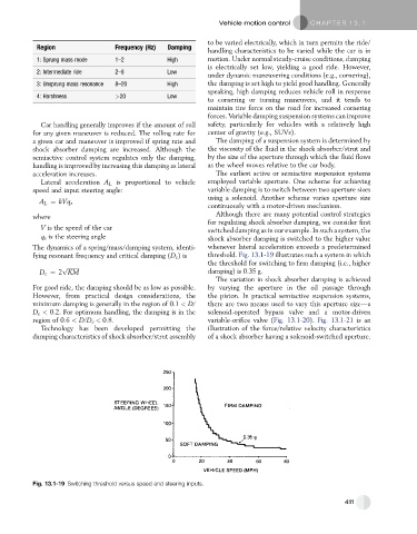
The dynamics of a spring/mass/damping system, identi- whenever lateral acceleration exceeds a predetermined
fying resonant frequency and critical damping (D c )is threshold. Fig. 13.1-19 illustrates such a system in which
the threshold for switching to firm damping (i.e., higher
p ffiffiffiffiffiffiffiffiffi
D c ¼ 2 KM damping) is 0.35 g.
The variation in shock absorber damping is achieved
For good ride, the damping should be as low as possible. by varying the aperture in the oil passage through
However, from practical design considerations, the the piston. In practical semiactive suspension systems,
minimum damping is generally in the region of 0.1 < D/ there are two means used to vary this aperture sizeda
D c < 0.2. For optimum handling, the damping is in the solenoid-operated bypass valve and a motor-driven
region of 0.6 < D/D c < 0.8. variable-orifice valve (Fig. 13.1-20). Fig. 13.1-21 is an
Technology has been developed permitting the illustration of the force/relative velocity characteristics
damping characteristics of shock absorber/strut assembly of a shock absorber having a solenoid-switched aperture.
Fig. 13.1-19 Switching threshold versus speed and steering inputs.
411