
Page 401 - Automotive Engineering Powertrain Chassis System and Vehicle Body
P. 401
CHAP TER 1 3. 1 Vehicle motion control
lateral force that maintains directional control of the car On the otherhand, m L decreases steadily with increasing
is shown as F L in Fig. 13.1-13. S such that for fully locked wheels the lateral force has its
The wheel angular speed begins to decrease, causing lowest value. For wet or icy roads, m L at S ¼ 100% is so low
a difference between the vehicle speed U and the tire that the lateral force is insufficient to maintain directional
speed over the road (i.e., wR). In effect, the tire slips control of the vehicle. However, directional control can
relative to the road surface. The amount of slip (S) de- often be maintained even in poor braking conditions if slip
termines the braking force and lateral force. The slip, as is optimally controlled. This is essentially the function of
a percentage of car speed, is given by the ABS, which performs an operation equivalent to
pumping the brakes(as done by experienced drivers before
U wR the development of ABS). In ABS-equipped cars under
S ¼ 100%
U marginal or poor braking conditions, the driver simply
applies a steady brake force and the system adjusts tire slip
Note: A rolling tire has slip S ¼ 0, and a fully locked to optimum value automatically.
tire has S ¼ 100%. In a typical ABS configuration, control over slip is
The braking and lateral forces are proportional to the effected by controlling the brake line pressure under
normal force (from the weight of the car) acting on the electronic control. The configuration for ABS is shown in
tire/road interface (N in Fig. 13.1-13) and the friction Fig. 13.1-12. This ABS regulates or modulates brake
coefficients for braking force ðF Þ and lateral force ðF L Þ: pressure to maintain slip as near to optimum as possible
b
(e.g., at S o in Fig. 13.1-14). The operation of this ABS is
F ¼ Nm b based on estimating the torque T w applied to the wheel at
b
F L ¼ Nm L the road surface by the braking force F b :
T w ¼ RF b
where
In opposition to this torque is the braking torque T b
m b is the braking friction coefficient applied to the disk by the calipers in response to brake
m L is the lateral friction coefficient
pressure P:
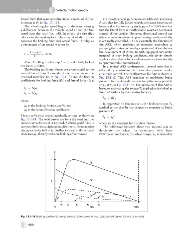
These coefficients depend markedly on slip, as shown in T ¼ k P
Fig. 13.1-14. The solid curves are for a dry road and the b b
dashed curves for a wet or icy road. As brake pedal force is where k b is a constant for the given brakes.
increased fromzero, slipincreases fromzero. Forincreasing The difference between these two torques acts to
slip, m b increases to S ¼ S o . Further increase in slip actually decelerate the wheel. In accordance with basic
decreases m b , thereby reducing braking effectiveness. Newtonian mechanics, the wheel torque T w is related to
Fig. 13.1-14 Braking coefficients versus tire slip (solid curves for dry road, dashed curves for wet or icy road).
406