
Page 396 - Automotive Engineering Powertrain Chassis System and Vehicle Body
P. 396
Vehicle motion control C HAPTER 13.1
FROM DATA BUS OF
CRUISE CONTROL
PARALLEL LOAD
SERIAL DOWN COUNT Z
C K
BINARY COUNTER
COIL 1
OF STEPPER
MOTOR
PHASE A A1
OSCILLATOR
A2
PHASE B
OSCILLATOR COIL 2
OF STEPPER
A3 MOTOR
A4
SB
SB
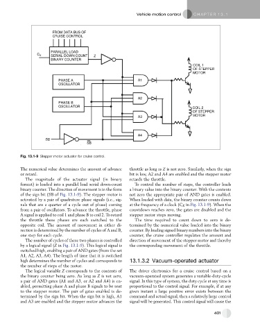
Fig. 13.1-9 Stepper motor actuator for cruise control.
The numerical value determines the amount of advance throttle as long as Z is not zero. Similarly, when the sign
or retard. bit is low, A2 and A4 are enabled and the stepper motor
The magnitude of the actuator signal (in binary retards the throttle.
format) is loaded into a parallel load serial down-count To control the number of steps, the controller loads
binary counter. The direction of movement is in the form a binary value into the binary counter. With the contents
of the sign bit (SB of Fig. 13.1-9). The stepper motor is not zero the appropriate pair of AND gates is enabled.
activated by a pair of quadrature phase signals (i.e., sig- When loaded with data, the binary counter counts down
nals that are a quarter of a cycle out of phase) coming at the frequency of a clock (C K in Fig. 13.1-9). When the
from a pair of oscillators. To advance the throttle, phase countdown reaches zero, the gates are disabled and the
A signal is applied to coil 1 and phase B to coil 2. To retard stepper motor stops moving.
the throttle these phases are each switched to the The time required to count down to zero is de-
opposite coil. The amount of movement in either di- termined by the numerical value loaded into the binary
rection is determined by the number of cycles of A and B, counter. By loading signed binary numbers into the binary
one step for each cycle. counter, the cruise controller regulates the amount and
The number of cycles of these two phases is controlled direction of movement of the stepper motor and thereby
by a logical signal (Z in Fig. 13.1-9). This logical signal is the corresponding movement of the throttle.
switched high, enabling a pair of AND gates (from the set
A1, A2, A3, A4). The length of time that it is switched
high determines the number of cycles and corresponds to 13.1.3.2 Vacuum-operated actuator
the number of steps of the motor.
The logical variable Z corresponds to the contents of The driver electronics for a cruise control based on a
the binary counter being zero. As long as Z is not zero, vacuum-operated system generates a variable-duty-cycle
a pair of AND gates (A1 and A3, or A2 and A4) is en- signal. In this type of system, the duty cycle at any time is
abled, permitting phase A and phase B signals to be sent proportional to the control signal. For example, if at any
to the stepper motor. The pair of gates enabled is de- given instant a large positive error exists between the
termined by the sign bit. When the sign bit is high, A1 command and actual signal, then a relatively large control
and A3 are enabled and the stepper motor advances the signal will be generated. This control signal will cause the
401