
Page 393 - Automotive Engineering Powertrain Chassis System and Vehicle Body
P. 393
CHAP TER 1 3. 1 Vehicle motion control
in the line of sight from source to detector. The light
detector produces an output voltage whenever a pulse of
light from the light source passes through a slot to the
detector. The number of pulses generated per second is
proportional to the number of slots in the disk and the
vehicle speed:
f ¼ NSK
where
f is the frequency in pulses per second
N is the number of slots in the sensor disk
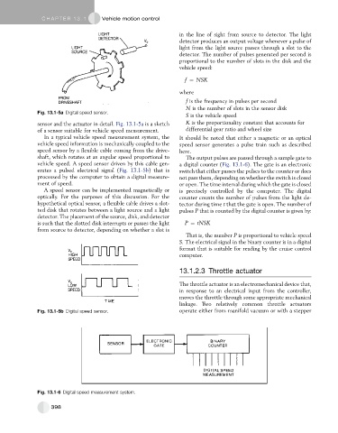
Fig. 13.1-5a Digital speed sensor.
S is the vehicle speed
sensor and the actuator in detail. Fig. 13.1-5a is a sketch K is the proportionality constant that accounts for
of a sensor suitable for vehicle speed measurement. differential gear ratio and wheel size
In a typical vehicle speed measurement system, the It should be noted that either a magnetic or an optical
vehicle speed information is mechanically coupled to the speed sensor generates a pulse train such as described
speed sensor by a flexible cable coming from the drive- here.
shaft, which rotates at an angular speed proportional to The output pulses are passed through a sample gate to
vehicle speed. A speed sensor driven by this cable gen- a digital counter (Fig. 13.1-6). The gate is an electronic
erates a pulsed electrical signal (Fig. 13.1-5b) that is switch that either passes the pulses to the counter or does
processed by the computer to obtain a digital measure- not pass them, depending on whether the switch is closed
ment of speed. or open. The time interval during which the gate is closed
A speed sensor can be implemented magnetically or is precisely controlled by the computer. The digital
optically. For the purposes of this discussion. For the counter counts the number of pulses from the light de-
hypothetical optical sensor, a flexible cable drives a slot- tector during time t that the gate is open. The number of
ted disk that rotates between a light source and a light pulses P that is counted by the digital counter is given by:
detector. The placement of the source, disk, and detector
is such that the slotted disk interrupts or passes the light P ¼ tNSK
from source to detector, depending on whether a slot is
That is, the number P is proportional to vehicle speed
S. The electrical signal in the binary counter is in a digital
format that is suitable for reading by the cruise control
computer.
13.1.2.3 Throttle actuator
The throttle actuator is an electromechanical device that,
in response to an electrical input from the controller,
moves the throttle through some appropriate mechanical
linkage. Two relatively common throttle actuators
Fig. 13.1-5b Digital speed sensor. operate either from manifold vacuum or with a stepper
Fig. 13.1-6 Digital speed measurement system.
398