
Page 389 - Automotive Engineering Powertrain Chassis System and Vehicle Body
P. 389
CHAP TER 1 3. 1 Vehicle motion control
ACTUAL CONTROL
SPEED SIGNAL THROTTLE
CONTROLLER
S 1 ACTUATOR
COMMAND
SPEED
ELECTRICAL
POWER
S 2 TO DRIVE
AXLES
SPEED
AIR ENGINE
SENSOR
THROTTLE
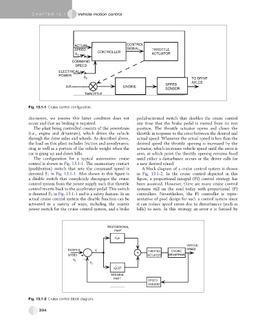
Fig. 13.1-1 Cruise control configuration.
discussion, we assume this latter condition does not pedal-activated switch that disables the cruise control
occur and that no braking is required. any time that the brake pedal is moved from its rest
The plant being controlled consists of the powertrain position. The throttle actuator opens and closes the
(i.e., engine and drivetrain), which drives the vehicle throttle in response to the error between the desired and
through the drive axles and wheels. As described above, actual speed. Whenever the actual speed is less than the
the load on this plant includes friction and aerodynamic desired speed the throttle opening is increased by the
drag as well as a portion of the vehicle weight when the actuator, which increases vehicle speed until the error is
car is going up and down hills. zero, at which point the throttle opening remains fixed
The configuration for a typical automotive cruise until either a disturbance occurs or the driver calls for
control is shown in Fig. 13.1-1. The momentary contact a new desired speed.
(pushbutton) switch that sets the command speed is A block diagram of a cruise control system is shown
denoted S 1 in Fig. 13.1-1. Also shown in this figure is in Fig. 13.1-2. In the cruise control depicted in this
a disable switch that completely disengages the cruise figure, a proportional integral (PI) control strategy has
control system from the power supply such that throttle been assumed. However, there are many cruise control
control reverts back to the accelerator pedal. This switch systems still on the road today with proportional (P)
is denoted S 2 in Fig. 13.1-1 and is a safety feature. In an controllers. Nevertheless, the PI controller is repre-
actual cruise control system the disable function can be sentative of good design for such a control system since
activated in a variety of ways, including the master it can reduce speed errors due to disturbances (such as
power switch for the cruise control system, and a brake hills) to zero. In this strategy an error e is formed by
PROPORTIONAL
PART
K e
P
VEHICLE
DESIRED E THROTTLE ENGINE SPEED
SPEED ACTUATOR DRIVETRAIN
V d
V a
K∫eDT
I
INTEGRAL
PART
SPEED
SENSOR
Fig. 13.1-2 Cruise control block diagram.
394