
Page 384 - Automotive Engineering Powertrain Chassis System and Vehicle Body
P. 384
Braking systems C HAPTER 12.1
2
3 1
Disc
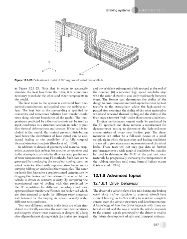
Figure 12.1-23 Finite element model of 10 segment of vented disc and hub.
in Figure 12.1-23. Note that in order to accurately and the vehicle is subsequently left to stand at the end of
simulate the heat loss from the rotor, it is sometimes the descent; (ii) a repeated high speed autobahn stop
necessary to include the wheel and other components in with the rotor allowed to cool only moderately between
the model. stops. The former test determines the ability of the
The heat input to the system is estimated from the- design to limit temperature build-up in the rotor by heat
oretical consideration and applied over the rubbing sur- transfer to the atmosphere whilst the high-speed re-
face. The heat loss to the surrounding is specified by peated stop examines the ability of the rotor material to
convective and sometimes radiative heat transfer condi- withstand repeated thermal cycling and the ability of the
tions along relevant boundaries of the model. The tem- friction pair to resist ‘fade’ under these severe conditions.
peratures predicted by a thermal analysis can be used as Friction performance cannot easily be predicted by
input conditions to a structural analysis in order to pre- the FE approach and there remains a requirement for
dict thermal deformations and stresses. If the pad is in- dynamometer testing to determine the fade-and-wear
cluded in the model, the contact pressure distribution characteristics of every new friction pair. The dyna-
(and hence the distribution of heat input) can be esti- mometer can either be a full-scale device or a small
mated leading to the possibility of a fully coupled sample rig in which the geometry and loading conditions
thermal-structural analysis (Brooks et al., 1994). are scaled to give an accurate representation of the actual
In addition to details of geometry and material prop- brake. These tests will not only give data on friction
erties, accurate date on heat loss to other components and performance over a wide range of conditions but can also
to the atmosphere are vital to allow accurate predictions be used to determine the MOT of the pad and rotor
of rotor temperatures using FE methods. Such data can be materials by progressively increasing the temperature at
generated by conducting the so-called ‘cooling tests’ on the rubbing interface until some form of failure occurs
actual vehicles fitted with representative brake rotors (Grieve et al., 1996).
carrying rubbing or embedded thermocouples. The rotor
surface is first heated to a predetermined temperature by
dragging the brakes and then allowed to cool whilst the 12.1.6 Advanced topics
vehicle is driven at constant velocity. By comparing the
experimental rate of cooling with that predicted by 12.1.6.1 Driver behaviour
the FE simulation for different boundary conditions,
optimized heat transfer coefficients can be derived which The driver of a vehicle plays a key role during any braking
are then assumed to apply for different rotor materials event since his/her reactions to external stimuli have
and factored for the varying air stream velocity under a direct bearing on his/her ability to maintain complete
different test conditions. control over the vehicle trajectory and deceleration rate.
Two very different vehicle brake tests are often sim- A knowledge of how the driver interacts with these ex-
ulated to critically examine the maximum temperatures ternal stimuli and the way in which the vehicle responds
and integrity of new rotor materials or designs: (i) a long to the control signals generated by the driver is vital to
slow Alpine descent during which the brakes are dragged the future development of safe road transport systems.
387