
Page 379 - Automotive Engineering Powertrain Chassis System and Vehicle Body
P. 379
CHAP TER 1 2. 1 Braking systems
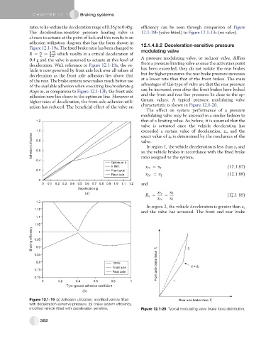
ratio, to lie within the deceleration range of 0.35g to 0.45g. efficiency can be seen through comparison of Figure
The deceleration-sensitive pressure limiting valve is 12.1-19b (valve fitted) to Figure 12.1-13c (no valve).
chosen to actuate at the point of lock and this results in an
adhesion utilization diagram that has the form shown in 12.1.4.8.2 Deceleration-sensitive pressure
Figure 12.1-19a. The fixed brake ratio has been changed to
R ¼ x f ¼ 0:73 which results in a critical deceleration of modulating valve
x r 0:27
0.4 g and the valve is assumed to actuate at this level of A pressure modulating valve, or reducer valve, differs
deceleration. With reference to Figure 12.1-19a, the ve- from a pressure limiting valve as once the activation point
hicle is now governed by front axle lock over all values of has been exceeded, they do not isolate the rear brakes
deceleration as the front axle adhesion lies above that but for higher pressures the rear brake pressure increases
of the rear. The brake system now makes much better use at a lower rate than that of the front brakes. The main
of the available adhesion when executing low/moderate g advantages of this type of valve are that the rear pressure
stops as, in comparison to Figure 12.1-13b, the front axle can be increased even after the front brakes have locked
adhesion now lies closer to the optimum line. However at and the front and rear line pressures lie close to the op-
higher rates of deceleration, the front axle adhesion utili- timum values. A typical pressure modulating valve
zation has reduced. The beneficial effect of the valve on characteristic is shown in Figure 12.1-20.
The effect on system performance of a pressure
modulating valve may be assessed in a similar fashion to
1.2 that of a limiting value. As before, it is assumed that the
valve is actuated once the vehicle deceleration has
1.0 exceeded a certain value of deceleration, z v , and the
Adhesion utilization 0.8 valve.
exact value of z v is determined by the mechanics of the
In region 1, the vehicle deceleration is less than z v and
0.6
so the vehicle brakes in accordance with the fixed brake
0.4 ratio assigned to the system,
Optimum k
k limit x rv ¼ x r (12.1.87)
0.2 Front axle
Rear axle x fv 0 ¼ x f (12.1.88)
0
0 0.1 0.2 0.3 0.4 0.5 0.6 0.7 0.8 0.9 1.0 1.1 1.2 and
Deceleration g
(a) x fv x f
R v ¼ ¼ (12.1 89)
x rv x r
1.2
In region 2, the vehicle deceleration is greater than z v
1.15
and the valve has actuated. The front and rear brake
1.1
1.05
Braking efficiency 0.95
1
0.9
0.85 2
0.8 100% Front axle brake force T f
Front axle z = z v
0.75
Rear axle
0.70
0 0.2 0.4 0.6 0.8 1 1
Tyre–ground adhesion coefficient
(b)
Figure 12.1-19 (a) Adhesion utilization, modified vehicle fitted Rear axle brake force T r
with deceleration-sensitive pressure, (b) brake system efficiency,
modified vehicle fitted with deceleration sensitive. Figure 12.1-20 Typical modulating valve brake force distribution.
382