
Page 376 - Automotive Engineering Powertrain Chassis System and Vehicle Body
P. 376
Braking systems C HAPTER 12.1
It is therefore feasible to apply the preceding ideas to vehicle body to be rigid and that the front and rear sus-
the formulation of a fixed brake ratio that will invariably pension spring rates, k f and k r , are linear. The spring rates
lead to front axle lock and this is commonly applied to used are the axle rates.
the design of brake systems found on passenger vehicles. The opposed spring forces generated during a braking
The fixed brake ratio is chosen such that for the unladen event are equal to the load transfer that takes place and
case both front and rear axles are on the verge of lock so are equal to
when the vehicle undertakes a 1g stop on a road surface Pzh
that has a tyre–ground adhesion coefficient of unity. y r
Under such conditions, the brake ratio is equal to: l
and this causes the vehicle to go down at the front and
move upwards at the rear as shown in Figure 12.1-16.
x f F þ Ph
f
l
¼ (12.1.67) Thus, on the assumption of linear springing, the com-
x r F r Ph pression travel at the front is:
l
Pzh
y ¼ l (12.1.68)
and on all surfaces where the tyre–ground adhesion is less f k f
than unity, the braking will be limited by front axle lock.
The effect of axle lock on vehicle stability may also be and the corresponding travel at the rear is:
assessed through the formal derivation of the equation of
motion associated with the yawing of the vehicle. Anal- Pzh
l
ysis of the same cases of axle lock leads to identical y r ¼ k r (12.1.69)
conclusions regarding the behaviour of the vehicle with
the added benefit that measures of yaw acceleration, The pitch angle, q, in degrees, adopted by the vehicle
velocity and displacement can be deduced. body is therefore given by:
y þ y r 360
f
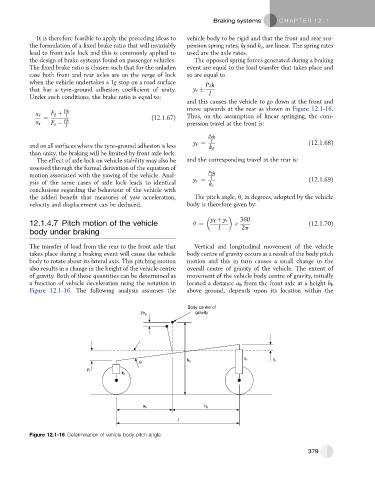
12.1.4.7 Pitch motion of the vehicle q ¼ (12.1.70)
l 2p
body under braking
The transfer of load from the rear to the front axle that Vertical and longitudinal movement of the vehicle
takes place during a braking event will cause the vehicle body centre of gravity occurs as a result of the body pitch
body to rotate about its lateral axis. This pitching motion motion and this in turn causes a small change in the
also results in a change in the height of the vehicle centre overall centre of gravity of the vehicle. The extent of
of gravity. Both of these quantities can be determined as movement of the vehicle body centre of gravity, initially
a function of vehicle deceleration using the notation in located a distance a b from the front axle at a height h b
Figure 12.1-16. The following analysis assumes the above ground, depends upon its location within the
Body centre of
gravity
δh b
θ h b k r y r
y f
k f
a b b b
l
Figure 12.1-16 Determination of vehicle body pitch angle.
379