
Page 378 - Automotive Engineering Powertrain Chassis System and Vehicle Body
P. 378
Braking systems C HAPTER 12.1
5
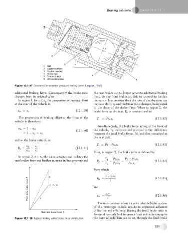
D 2
D 1
1
6
3 α
1 Ball
2 Support surface
3 Control opening
4 Brake fluid
5 To rear brakes 2
6 Differential piston 4
Figure 12.1-17 Deceleration-sensitive pressure limiting valve (Limpert, 1992).
additional braking force. Consequently the brake ratio the rear brakes can no longer generate additional braking
changes from its original value. force. As the front brakes are able to respond to further
In region 1, for z z v , the proportion of braking effort increase in line pressure then the rate of deceleration can
at the rear of the vehicle is: increase above z v and the brake ratio changes, being equal
to the slope of the dashed line. When in region 2, the
x rv ¼ x r (12.1.79) brake force at the rear, T r , is constant and is:
The proportion of braking effort at the front of the
T r ¼ Pz v x r (12.1.82)
vehicle is therefore:
Simultaneously, the brake force acting at the front of
x fv ¼ 1 x rv (12.1.80) the vehicle, T f , increases and is equal to the difference
¼ 1 x r ¼ x f between the total brake force, Pz, and that sustained at
the rear axle
and so the brake ratio R v is:
x fv x f T ¼ Pz Pz v x r (12.1.83)
f
R v ¼ ¼ (12.1 81)
x rv x r
Thus, in region 2, the brake ratio is defined by:
In region 2, z > z v , the valve actuates and isolates the
rear brakes from any further increase in line pressure and R v ¼ T f ¼ Pzx fv ¼ Pz Pz v x r (12.1.84)
T r Pzx rv Pz v x r
from which (12.1.85)
z z v x r
2
Front axle brake force T f z = z v and fv z v x r z (12.1.86)
x
¼
x rv ¼
z
1
The incorporation of such a valve into the brake system
of the prototype vehicle results in improved adhesion
utilization and efficiency. Biasing the fixed brake ratio in
Rear axle brake force T r
favour of rear axle lock improves front axle adhesion up to
Figure 12.1-18 Typical limiting valve brake force distribution. the point of lock. This can be set, through the fixed brake
381