
Page 375 - Automotive Engineering Powertrain Chassis System and Vehicle Body
P. 375
CHAP TER 1 2. 1 Braking systems
vehicle to generate the lateral forces required to maintain initial slip angle a. Thus, when the front axle is locked,
directional control and stability is severely impaired. the vehicle is unable to respond to any steering inputs and
Irregularities in the road surface or lateral forces can so its forward motion continues in a straight line.
cause the vehicle to deviate from its direction of travel.
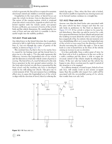
The nature of the ensuing motion, which is rotational 12.1.4.6.2 Rear axle lock
about the vehicle vertical axis, depends on which axle has
Assume now that the fixed brake ratio associated with
locked together with the vehicle speed, tyre–ground the same vehicle has been changed such that the rear
friction coefficient, yaw moment of inertia of the vehicle axle locks in preference to the front as depicted in
body and the vehicle dimensions. By considering the two Figure 12.1-15. If the vehicle is subject to the same lat-
cases of front and rear axle lock it is possible to derive eral disturbance, then this can only be reacted by a side
useful insight into the stability problem:
force generated between the front wheels and ground and
the resulting moment about the vehicle centre of gravity
12.1.4.6.1 Front axle lock has a magnitude of S f a. In contrast, this yaw moment now
Any disturbance in the lateral direction due to gradient, has a destabilizing effect as it causes the longitudinal axis
sidewind or left to right brake imbalance produces a side of the vehicle to move away from the direction of travel,
force F y that acts through the centre of gravity of the thereby increasing the vehicle slip angle a. This in turn
vehicle, as shown in Figure 12.1-14. leads to a rise in lateral force at the front of the vehicle
The resultant force F R that is due to the inertia force causing an increase in yaw acceleration.
F x caused by the braking event and the lateral force F y It is thus preferable, from a safety point of view, for
gives rise to a slip angle a. This slip angle represents the the front axle to lock in preference to the rear as this is
difference between the longitudinal axis of the vehicle a stable condition and the driver is able to regain di-
and the direction in which the vehicle centre of gravity is rectional control of the vehicle simply by releasing the
moving. The lateral force F y must be balanced by the side brakes. If the rear axle has locked and the vehicle has
forces generated in the tyre–ground contact patches. As begun to spin, driver reaction must be rapid if control of
the front axle is locked, no side force is generated by the the situation is to be regained.
front wheels and the resulting side force is developed In a collision situation, a frontal impact, linked to front
solely by the still rolling rear wheels. This gives rise to axle lock, will usually result in less serious occupant
a total moment of S r b. This yaw moment has a stabilizing injury than the possible side impact that could well be
effect since it causes the longitudinal axis of the vehicle associated with the uncontrolled yawing of the vehicle
to align with the direction of travel, thereby reducing the that results from rear axle lock.
S f /2
S f /2 F x
F R
a α
T f /2 T f /2
F y
x
b
y
T r /2 T r /2
Figure 12.1-15 Rear axle lock.
378