
Page 371 - Automotive Engineering Powertrain Chassis System and Vehicle Body
P. 371
CHAP TER 1 2. 1 Braking systems
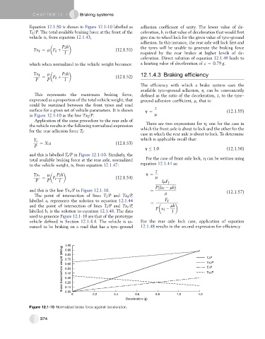
Equation 12.1.50 is shown in Figure 12.1-10 labelled as adhesion coefficient of unity. The lower value of de-
T =P. The total available braking force at the front of the celeration, b, is that value of deceleration that would first
f
vehicle is, from equation 12.1.43, give rise to wheel lock for the given value of tyre–ground
adhesion. In this instance, the rear axle will lock first and
Pzh the tyres will be unable to generate the braking force
Tx ¼ m F þ (12.1.51)
f
f
l required by the rear brakes at higher levels of de-
celeration. Direct solution of equation 12.1.48 leads to
which when normalized to the vehicle weight becomes: a limiting value of deceleration of z ¼ 0:79 g.
Tx f m Pzh 12.1.4.3 Braking efficiency
f
P ¼ P F þ l (12.1.52)
The efficiency with which a brake system uses the
available tyre–ground adhesion, h, can be conveniently
This represents the maximum braking force, defined as the ratio of the deceleration, z, to the tyre–
expressed as a proportion of the total vehicle weight, that ground adhesion coefficient, m, that is:
could be sustained between the front tyres and road
surface for a given set of vehicle parameters. It is shown h ¼ z (12.1.55)
in Figure 12.1-10 as the line Tx =P. m
f
Application of the same procedure to the rear axle of
There are two expressions for h; one for the case in
the vehicle results in the following normalized expression
which the front axle is about to lock and the other for the
for the rear adhesion force T r :
case in which the rear axle is about to lock. To determine
which is applicable recall that:
T r
¼ X r z (12.1.53)
P
h 1:0 (12.1.56)
and this is labelled T r /P in Figure 12.1-10. Similarly, the
total available braking force at the rear axle, normalized For the case of front axle lock, h can be written using
to the vehicle weight, is, from equation 12.1.47: equation 12.1.44 as:
z
Tx r m Pzh h ¼
¼ F r (12.1.54) m
P P l lmF f
Pðlx mhÞ
f
and this is the line Tx r /P in Figure 12.1-10. ¼ (12.1.57)
m
The point of intersection of lines T f /P and Tx f /P,
labelled a, represents the solution to equation 12.1.44 ¼ F f
and the point of intersection of lines T r /P and Tx r /P, mh
f
labelled b, is the solution to equation 12.1.48. The data P x l
used to generate Figure 12.1-10 are that of the prototype
vehicle defined in Section 12.1.4.4. The vehicle is as- For the rear axle lock case, application of equation
sumed to be braking on a road that has a tyre–ground 12.1.48 results in the second expression for efficiency
1.00
Brake force/vehicle weight (kN/kg) 0.70 T f /P
0.90
0.80
Tx f /P
0.60
T r /P
0.50
Tx f /P
0.40
0.30
0.20
0.10
0.00
0 0.2 0.4 0.6 0.8 1.0 1.2
Deceleration (g)
Figure 12.1-10 Normalized brake force against deceleration.
374