
Page 369 - Automotive Engineering Powertrain Chassis System and Vehicle Body
P. 369
CHAP TER 1 2. 1 Braking systems
varying the payload and so the changein mass from unladen y
to laden can be severe. The distribution and size of the
payload, which also governs the location of the centre of θ
gravity, may change on a daily basis or throughout a delivery
cycle in which the payload is discharged in stages. x
12.1.4.2 Braking with a constant D
brake ratio
Mg
The object of this analysis is to show how braking affects
the vertical loads carried by the front and rear axles. This
in turn leads to a way of determining the maximum de- R f T fr T f R r T rr T r
celeration attainable by a vehicle under specified condi-
a b
tions that does not result in axle lock.
If the front and rear axles are to be on the point of l
locking, then the braking forces T f and T r acting at each
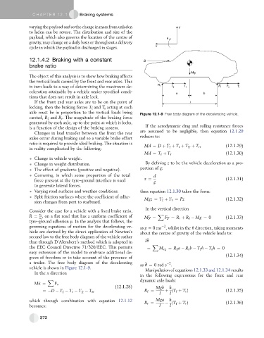
axle must be in proportion to the vertical loads being Figure 12.1-9 Free body diagram of the decelerating vehicle.
carried, R f and R r . The magnitude of the braking force
generated by each axle, up to the point at which it locks,
is a function of the design of the braking system. If the aerodynamic drag and rolling resistance forces
Changes in load transfer between the front the rear are assumed to be negligible, then equation 12.1.29
axles occur during braking and so a variable brake effort reduces to:
ratio is required to provide ideal braking. The situation is
Md ¼ D þ T þ T r þ T þ T rr (12.1.29)
f
fr
in reality complicated by the following:
Md ¼ T þ T r (12.1.30)
f
Change in vehicle weight.
Change in weight distribution. By defining z to be the vehicle deceleration as a pro-
The effect of gradients (positive and negative). portion of g:
Cornering, in which some proportion of the total d
force present at the tyre–ground interface is used z ¼ g (12.1.31)
to generate lateral forces.
Varying road surfaces and weather conditions. then equation 12.1.30 takes the form:
Split friction surfaces where the coefficient of adhe- Mgz ¼ T þ T r ¼ Pz (12.1.32)
sion changes from port to starboard. f
In the vertical direction
Consider the case for a vehicle with a fixed brake ratio, X
R ¼ x f , on a flat road that has a uniform coefficient of M€ y ¼ Fy ¼ R r þ R Mg ¼ 0 (12.1.33)
x r f
tyre–ground adhesion m. In the analysis that follows, the
governing equations of motion for the decelerating ve- as y =0 ms , whilst in the q direction, taking moments
2
hicle are derived by the direct application of Newton’s about the centre of gravity of the vehicle leads to:
second law to the free body diagram of the vehicle rather
€
than through D’Alembert’s method which is adopted in Iq X
the EEC Council Directive 71/320/EEC. This permits ¼ M cg ¼ R a R r b T h T r h ¼ 0
f
f
easy extension of the model to embrace additional de-
grees of freedom or to take account of the presence of (12.1.34)
a trailer. The free body diagram of the decelerating as q ¼ 0rad s .
2
€
vehicle is shown in Figure 12.1-9. Manipulation of equations 12.1.33 and 12.1.34 results
In the x direction
in the following expressions for the front and rear
X dynamic axle loads:
M€ x ¼ F x
(12.1.28) Mgb h
¼ D T T r T T rr R ¼ l þ ðT þ T r Þ (12.1.35)
f
f
fr
f
l
h
which through combination with equation 12.1.12 R r ¼ Mga ðT þ T r Þ (12.1.36)
becomes: l l f
372