
Page 367 - Automotive Engineering Powertrain Chassis System and Vehicle Body
P. 367
CHAP TER 1 2. 1 Braking systems
may account for a force equivalent to 0.03g when trav- of slip taking place at the tyre–road interface and so brake
elling at high speed. force and slip co-exist. The longitudinal slip of the tyre is
Gradient makes either a positive (uphill) or negative defined as a ratio:
(downhill) contribution to the total braking force
experienced by a vehicle. This force is simply the slip velocity in contact patch
slip ¼
component of the total vehicle weight acting in the forward velocity
plane of the road. v ur
¼ (12.1.24)
Drivetrain drag may either help or hinder the braking v
performance of a vehicle. If the vehicle is deceler-
ating faster than the components of the drivetrain where v is the forward velocity of the vehicle, u is the
would slow down under their own friction then angular velocity of the wheel and r the wheel radius.
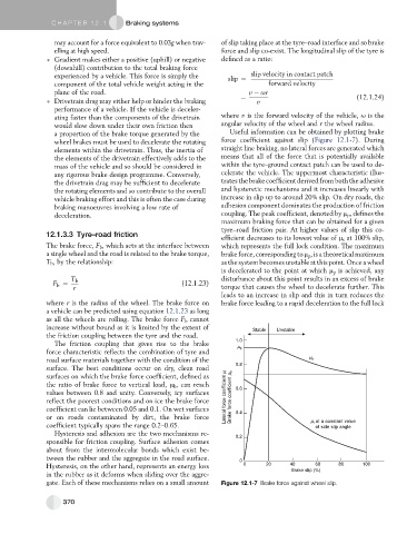
a proportion of the brake torque generated by the Useful information can be obtained by plotting brake
wheel brakes must be used to decelerate the rotating force coefficient against slip (Figure 12.1-7). During
elements within the drivetrain. Thus, the inertia of straight line braking, no lateral forces are generated which
the elements of the drivetrain effectively adds to the means that all of the force that is potentially available
mass of the vehicle and so should be considered in within the tyre–ground contact patch can be used to de-
any rigorous brake design programme. Conversely, celerate the vehicle. The uppermost characteristic illus-
the drivetrain drag may be sufficient to decelerate trates the brake coefficient derived from both the adhesive
the rotating elements and so contribute to the overall and hysteretic mechanisms and it increases linearly with
vehicle braking effort and this is often the case during increase in slip up to around 20% slip. On dry roads, the
braking manoeuvres involving a low rate of adhesion component dominates the production of friction
deceleration. coupling. The peak coefficient, denoted by m p , defines the
maximum braking force that can be obtained for a given
tyre–road friction pair. At higher values of slip this co-
12.1.3.3 Tyre–road friction
efficient decreases to its lowest value of m s at 100% slip,
The brake force, F b , which acts at the interface between which represents the full lock condition. The maximum
a single wheel and the road is related to the brake torque, brake force, corresponding to m p , is a theoretical maximum
T b , by the relationship: as the system becomes unstable at thispoint. Once a wheel
is decelerated to the point at which m p is achieved, any
T b disturbance about this point results in an excess of brake
F ¼ (12.1.23)
b
r torque that causes the wheel to decelerate further. This
leads to an increase in slip and this in turn reduces the
where r is the radius of the wheel. The brake force on brake force leading to a rapid deceleration to the full lock
a vehicle can be predicted using equation 12.1.23 as long
as all the wheels are rolling. The brake force F b cannot
increase without bound as it is limited by the extent of Stable Unstable
the friction coupling between the tyre and the road.
1.0
The friction coupling that gives rise to the brake
μ p
force characteristic reflects the combination of tyre and
road surface materials together with the condition of the μ b
0.8
surface. The best conditions occur on dry, clean road
μ l μ b
surfaces on which the brake force coefficient, defined as
the ratio of brake force to vertical load, m b , can reach 0.6
values between 0.8 and unity. Conversely, icy surfaces
reflect the poorest conditions and on ice the brake force Lateral force coefficient Brake force coefficient
coefficient can lie between 0.05 and 0.1. On wet surfaces 0.4
or on roads contaminated by dirt, the brake force μ l at a constant value
coefficient typically spans the range 0.2–0.65. of side slip angle
Hysteresis and adhesion are the two mechanisms re-
0.2
sponsible for friction coupling. Surface adhesion comes
about from the intermolecular bonds which exist be-
tween the rubber and the aggregate in the road surface.
0
Hysteresis, on the other hand, represents an energy loss 0 20 40 60 80 100
Brake slip (%)
in the rubber as it deforms when sliding over the aggre-
gate. Each of these mechanisms relies on a small amount Figure 12.1-7 Brake force against wheel slip.
370