
Page 368 - Automotive Engineering Powertrain Chassis System and Vehicle Body
P. 368
Braking systems C HAPTER 12.1
condition. It is worthwhile to note that ABSs make use of
Table 12.1-1 Prototype vehicle parameters
this phenomenon.
The negotiation of a bend requires a vehicle to develop Parameter Symbol Units Value
a lateral force in the tyre–ground plane through the de-
formation of the tyre carcass brought about by a slip angle. Mass M kg 980
Wheel base I m 2.45
Lateral forces, characterized by the coefficient m 1 , being Height of centre of gravity h m 0.47
a function of slip angle, and longitudinal forces, charac- above ground
terized by m b thus co-exist and compete for the finite Static axle loads (% of total) Front F f – 65
amount of force that is available within the contact patch. Rear F r – 35
A typical lateral force coefficient is shown on Figure 12.1-7 Fixed brake ratio Front x f – 75
fora given value of slip angle. It has a maximum value when R ¼ x f ð%Þ Rear x r – 25
the brake slip is zero and falls with increase in brake slip. x r
The minimum value occurswhen the wheel has locked and
is unable to generate further lateral force. axle are equal and so the following analyses treat axle
loading rather than the individual wheels.
The vertical load due to the vehicle mass is simply:
12.1.4 Brake proportioning and
adhesion utilization P ¼ Mg (12.1.25)
where g is the acceleration due to gravity.
The vertical loads carried by the front and rear wheels of Taking moments about the rear tyre–road contact
a rigid, two axle vehicle are not, in general, equal. In gives:
order to efficiently utilize the available tyre–road adhe-
sion the braking effort must be apportioned between the Pb
front and rear of the vehicle in an intelligent and con- F ¼ l (12.1.26)
f
trolled fashion. Failure to do so could result in any of the
following: and moments about the front tyre–road contact provides
a value of the vertical load acting at the rear axle given by:
A vehicle being unable to generate the necessary
deceleration for a given pedal pressure. Pa
Front axle lock, in which the vehicle remains stable F r ¼ l (12.1.27)
yet suffers from a loss of steering control.
Rear axle lock that causes the vehicle to become The influence of the fore–aft location of the centre of
unstable. gravity on the vertical wheel loads, due to change in
loading conditions is readily apparent from equations
The terms front wheel lock and rear wheel lock can 12.1.26 and 12.1.27.
be alternatively labelled front axle over brakes and rear The maximum payload of a passenger car forms only
axle over brakes, respectively. In this section factors a fraction of the unladen vehicle mass and the inherent
influencing the fore–aft axle loads are identified and their space restrictions limit the extent to which the centre of
effect on braking examined, concentrating on vehicles gravity can move. For a light rigid truck, such as a transit
that have a fixed brake ratio. Devices used to modify the type van or pickup, there exists considerable scope for
braking ratio are discussed in the latter part of this section
and their effect on braking performance evaluated.
The theory developed in Sections 12.1.4.2–12.1.4.4
and 12.1.4.8 is applied to the analysis of the braking re-
quirements of a fictitious two axle road vehicle. This
vehicle is assumed to be unladen and is described by the
parameters given in Table 12.1-1.
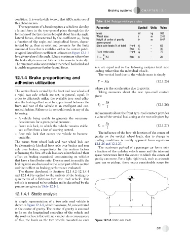
12.1.4.1 Static analysis
F f F r
P
A simple representation of a two axle road vehicle is
shown inFigure12.1-8, which hasa mass, M, concentrated a b
at the centre of gravity. The centre of gravity is assumed
to lie on the longitudinal centreline of the vehicle and l
the road surface is flat with no camber. As a consequence
of this, the loads on the two wheels mounted on each Figure 12.1-8 Static axle loads.
371