
Page 365 - Automotive Engineering Powertrain Chassis System and Vehicle Body
P. 365
CHAP TER 1 2. 1 Braking systems
Deceleration (m s –2 ) a f
Time (s)
t 0 t 1 t 2 t 3 t 4
u
Velocity (m s –1 )
Time (s)
t 0 t 1 t 2 t 3 t 4
Displacement (m) Stopping distance S s
Braking distance S b
Time (s)
t 0 t 1 t 2 t 3 t 4
Braking time
Stopping time
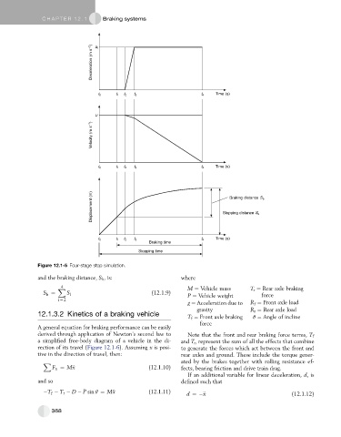
Figure 12.1-5 Four-stage stop simulation.
and the braking distance, S b , is: where
X M ¼ Vehicle mass T r ¼ Rear axle braking
4
S ¼ S i (12.1.9) P ¼ Vehicle weight force
b
i ¼ 2
g ¼ Acceleration due to R f ¼ Front axle load
gravity R r ¼ Rear axle load
12.1.3.2 Kinetics of a braking vehicle
T f ¼ Front axle braking q ¼ Angle of incline
force
A general equation for braking performance can be easily
derived through application of Newton’s second law to Note that the front and rear braking force terms, T f
a simplified free-body diagram of a vehicle in the di- and T r , represent the sum of all the effects that combine
rection of its travel (Figure 12.1-6). Assuming x is posi- to generate the forces which act between the front and
tive in the direction of travel, then: rear axles and ground. These include the torque gener-
X ated by the brakes together with rolling resistance ef-
F x ¼ M€ x (12.1.10) fects, bearing friction and drive train drag.
If an additional variable for linear deceleration, d,is
and so defined such that
T T r D P sin q ¼ M€ x (12.1.11) d ¼ € x (12.1.12)
f
368