
Page 366 - Automotive Engineering Powertrain Chassis System and Vehicle Body
P. 366
Braking systems C HAPTER 12.1
x which leads to
2
T Tx v v 2
ðx x 0 Þ¼ ¼ 0 f (12.1.18)
f
M M 2
where x is the distance travelled during the brake
application.
T f
When considering a stop, the final velocity v f is zero
R f
P
and so the stopping distance x is, from equation 12.1.18,
T r given by:
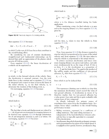
R r θ
Figure 12.1-6 Free body diagram of a braking vehicle. Mv 2 0
x ¼ (12.1.19)
2T
and the time, t b , taken to stop the vehicle is, from
then equation 12.1.11 becomes:
equation 12.1.16,
Md ¼ T þ T r þ D þ P sin q ¼ T (12.1.13) Mv 0 v 0
f
t ¼ ¼ (12.1.20)
b
T d
in which T is the sum of all those forces that contribute to
the overall braking effort. Thus, from equation 12.1.19 the distance required to
By considering the case of constant deceleration, stop the vehicle is proportional to the square of the initial
straightforward and fundamental relationships can be velocity and, from equation 12.1.20, the time taken to
derived that yield an appreciation of the physics which stop the vehicle is proportional to the initial velocity.
governs all braking events. To achieve maximum deceleration and hence mini-
From equation 12.1.13, the linear deceleration of mum stopping distance on a given road surface, each axle
a vehicle can be expressed as: must simultaneously be on the verge of lock. If this is
so then, if z is the deceleration as a proportion of
d
T dv g; z ¼ , and the brake force T is equal to the product of
g
d ¼ ¼ (12.1.14) the vehicle weight and the coefficient of tyre–ground
M dt
adhesion, P m , then from equation 12.1.13,
in which v is the forward velocity of the vehicle. Since
P z ¼ T ¼ P m (12.1.21)
the deceleration is assumed constant, then the total
brake force is also constant and so equation 12.1.14 can from which it can be deduced that
be integrated with respect to time between the limits of
the initial velocity, v 0 , to the final velocity, v f , to z ¼ m (12.1.22)
determine the duration of the braking event, t b .
On rearranging, equation 12.1.14 becomes: This represents a limiting case in which it is clear that
the maximum deceleration cannot exceed the value of
ð ð tyre–ground adhesion. A deceleration in excess of 1g
v f T t b
dv ¼ dt (12.1.15) therefore implies that the tyre–ground adhesion has
M
a value greater than unity and this is quite realizable with
v 0 0
certain types of tyre compound.
which leads to As already indicated, the primary source of
retardation force arises from the foundation brake. Sec-
T
v 0 v ¼ t b (12.1.16) ondary forces which contribute to the overall braking
f
M performance include:
The fact that velocity and displacement are related by Rolling resistance, expressed by a coefficient of
v ¼ dx=dt permits an expression for stopping distance to rolling resistance. The total rolling resistance is
be derived from equation 12.1.14 through substitution independent of the load distribution between axles
for dt and integration between v 0 and v f as before. On and the force is typically equivalent to a nominal
rearranging, equation 12.1.14 becomes: 0.01g deceleration.
ð ð Aerodynamic drag which depends on dynamic pressure
T x f v f
dx ¼ vdv (12.1.17) and is proportional to the square of the vehicle speed. It
M
x 0 v 0 is negligible at low speeds, however, aerodynamic drag
369