
Page 383 - Automotive Engineering Powertrain Chassis System and Vehicle Body
P. 383
CHAP TER 1 2. 1 Braking systems
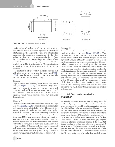
Heat input
Disc temperature MOT of material
Heat dissipation
(a) Strategy I (b) Strategy II (c) Strategy III
Figure 12.1-22 The ‘bucket-and-hole’ analogy.
‘bucket-and-hole’ analogy in which the rate of water Strategy III
flow into the bucket is taken to represent the heat flow Even smaller diameter bucket but much deeper with
into the disc and the height of the water level in the bucket moderately sized hole (see Figure 12.1-22c). This
represents the maximum temperature of the disc implies a material with high MOTwhich can be allowed
surface. A hole in the bucket represents the ability of the to run much hotter than current designs and so lose
disc to lose heat to the surroundings. The volume of the significant amounts of heat by radiation as well as more
bucket is therefore the heat capacity of the disc whilst the moderate amounts by conduction/convection. Carbon–
height is the MOTof the disc material. The question then carbon composites are a possibility here but, as men-
is how close does the level of water in the bucket get to tioned above, these are currently too expensive for
overflow! mass produced vehicles. High-temperature steels with
Consideration of the ‘bucket-and-hole’ analogy and good strength retention at temperatures well in excess of
with reference to the typical material properties of Table 1000 C may also be candidate materials under this
12.1-3, three distinct strategies for brake rotor materials heading. Such discs could perhaps be made much thinner
can be identified (Grieve et al., 1996): and without vents, and therefore also save significant
weight. However, there would be concerns over compati-
Strategy I ble friction materials and heat transfer to other compo-
Large diameter and relatively deep bucket with small nents in the underbody wheel arch area if discs were
hole (see Figure 12.1-22a). This implies a high volu- allowed to run much hotter than is currently the practice
metric heat capacity to store heat during braking and with cast iron.
a relatively high MOT but only moderate conductivity of
heat away from the rubbing surfaces. Current GI discs
represent such a system but some steels may also meet 12.1.5.4 Disc materials/design
these criteria. evaluation
Strategy II Ultimately, any new brake material or design must be
Smaller diameter and relatively shallow bucket but large validated by experimental trials on actual vehicles to
hole(seeFigure12.1-22b).Thisimpliessmallervolumetric allow accurately for model-specific parameters such as
heat capacity and a relatively low MOT. Hence, it is im- the effect of body trim on rotor cooling. However, much
portanttohavehigh conductivitytotransfer heat toother can be learnt about potential new rotor materials or
parts of the rotor and then the surroundings in order to designs by numerical simulations of critical brake tests
prevent temperature build-up at the rubbing surfaces. using finite element (FE) analysis. Such techniques re-
Aluminium MMC may meet these criteria but recent re- quire the rotor and/or stator geometry to be broken
search (Grieve et al., 1998) suggests that this can only be down into a number of small non-overlapping regions
successfully achieved for currently available MMCs if the known as elements which are assumed to be connected
brake rotor is redesigned to increase its thermal mass and to one another at certain points known as nodes. A 2D
cooling capability. Other materials that may be successful axisymmetric FE idealization can be used as a first ap-
with appropriate development include high reinforcement proximation but, for more accurate simulation of the
content MMCs and coated alloy discs but again there are heat flow and stresses, a 3D model is desirable such as
manufacturing, integrity and cost issues to be resolved. the 10 segment model of a brake disc and hub shown
386