
Page 392 - Automotive Engineering Powertrain Chassis System and Vehicle Body
P. 392
Vehicle motion control C HAPTER 13.1
a damping ratio of about 0.4. Finally, consider the solid the problem. This formulation correctly describes the
curve of Fig. 13.1-3c. This curve corresponds to critical concept for cruise control regardless of whether the
damping. This situation involves the most rapid response implementation is by analog or digital electronics. Cruise
of the car to a disturbance, with no overshoot. control is now mostly implemented digitally using a mi-
The importance of these performance curves is that croprocessor-based computer. For such a system, pro-
they demonstrate how the performance of a cruise con- portional and integral control computations are
trol system is affected by the controller gains. These gains performed numerically in the computer. A block diagram
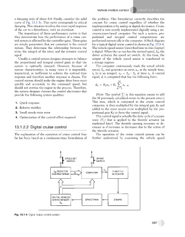
are simply parameters that are contained in the control for a typical digital cruise control is shown in Fig. 13.1-4.
system. They determine the relationship between the The vehicle speed sensor (described later in this chapter)
error, the integral of the error, and the actuator control is digital. When the car reaches the desired speed, S d , the
signal. driver activates the speed set switch. At this time, the
Usually a control system designer attempts to balance output of the vehicle speed sensor is transferred to
the proportional and integral control gains so that the a storage register.
system is optimally damped. However, because of The computer continuously reads the actual vehicle
system characteristics, in many cases it is impossible, speed, S a , and generates an error, e n , at the sample time,
impractical, or inefficient to achieve the optimal time t n (n is an integer). e n ¼ S S a at time t n . A control
d
response and therefore another response is chosen. The signal, d, is computed that has the following form:
control system should make the engine drive force react X
M
quickly and accurately to the command speed, but d n ¼ K P e n þ K I e n m
should not overtax the engine in the process. Therefore, m ¼ 1
the system designer chooses the control electronics that P
provide the following system qualities: (Note: The symbol in this equation means to add
the M previously calculated errors to the present error.)
1. Quick response This sum, which is computed in the cruise control
computer, is then multiplied by the integral gain K I and
2. Relative stability
added to the most recent error multiplied by the pro-
3. Small steady-state error portional gain K P to form the control signal.
4. Optimization of the control effort required This control signal is actually the duty cycle of a square
wave ðV c Þ that is applied to the throttle actuator (as
explained later). The throttle opening increases or de-
13.1.2.2 Digital cruise control creases as d increases or decreases due to the action of
the throttle actuator.
The explanation of the operation of cruise control thus The operation of the cruise control system can be
far has been based on a continuous-time formulation of further understood by examining the vehicle speed
Fig. 13.1-4 Digital cruise control system.
397