
Page 514 - Automotive Engineering Powertrain Chassis System and Vehicle Body
P. 514
CHAP TER 1 5. 1 Modelling and assembly of the full vehicle
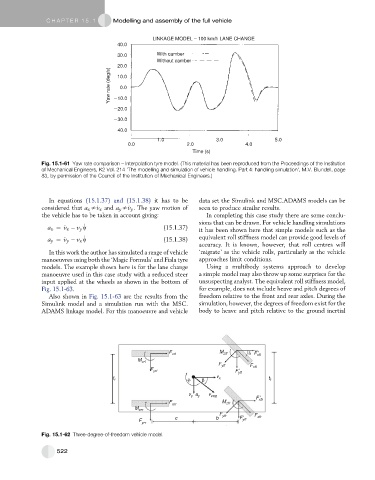
LINKAGE MODEL – 100 km/h LANE CHANGE
40.0
30.0 With camber
Without camber
20.0
Yaw rate (deg/s) 10.0
0.0
10.0
20.0
30.0
40.0
1.0 3.0 5.0
0.0 2.0 4.0
Time (s)
Fig. 15.1-61 Yaw rate comparison – Interpolation tyre model. (This material has been reproduced from the Proceedings of the Institution
of Mechanical Engineers, K2 Vol. 214 ‘The modelling and simulation of vehicle handling. Part 4: handling simulation’, M.V. Blundell, page
83, by permission of the Council of the Institution of Mechanical Engineers.)
In equations (15.1.37) and (15.1.38) it has to be data set the Simulink and MSC.ADAMS models can be
considered that a x s_ v x and a y s_ v y . The yaw motion of seen to produce similar results.
the vehicle has to be taken in account giving: In completing this case study there are some conclu-
sions that can be drawn. For vehicle handling simulations
a x ¼ _ v x v y w _ (15.1.37) it has been shown here that simple models such as the
_
a y ¼ _ v y v x w (15.1.38) equivalent roll stiffness model can provide good levels of
accuracy. It is known, however, that roll centres will
In this work the author has simulated a range of vehicle ‘migrate’ as the vehicle rolls, particularly as the vehicle
manoeuvres using both the ‘Magic Formula’ and Fiala tyre approaches limit conditions.
models. The example shown here is for the lane change Using a multibody systems approach to develop
manoeuvre used in this case study with a reduced steer a simple model may also throw up some surprises for the
input applied at the wheels as shown in the bottom of unsuspecting analyst. The equivalent roll stiffness model,
Fig. 15.1-63. for example, does not include heave and pitch degrees of
Also shown in Fig. 15.1-63 are the results from the freedom relative to the front and rear axles. During the
Simulink model and a simulation run with the MSC. simulation, however, the degrees of freedom exist for the
ADAMS linkage model. For this manoeuvre and vehicle body to heave and pitch relative to the ground inertial
M
F xrl zfl F xfl
M zrl
F yfl F xfl
F yrl F yfl
t r
v x t f
v y a y v cog
F xfr
F M zfr
xrr
M zrr
F F
c b yfr F xfr
F yfr
yrr
Fig. 15.1-62 Three-degree-of-freedom vehicle model.
522