
Page 509 - Automotive Engineering Powertrain Chassis System and Vehicle Body
P. 509
Modelling and assembly of the full vehicle C HAPTER 15.1
LUMPED MASS
MODEL
EQUIVALENT ROLL STIFFNESS
MODEL
SWING ARM MODEL
LINKAGE MODEL
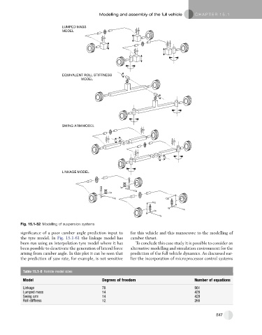
Fig. 15.1-52 Modelling of suspension systems
significance of a poor camber angle prediction input to for this vehicle and this manoeuvre to the modelling of
the tyre model. In Fig. 15.1-61 the linkage model has camber thrust.
been run using an interpolation tyre model where it has To conclude this case study it is possible to consider an
been possible to deactivate the generation of lateral force alternative modelling and simulation environment for the
arising from camber angle. In this plot it can be seen that prediction of the full vehicle dynamics. As discussed ear-
the prediction of yaw rate, for example, is not sensitive lier the incorporation of microprocessor control systems
Table 15.1-6 Vehicle model sizes
Model Degrees of freedom Number of equations
Linkage 78 961
Lumped mass 14 429
Swing arm 14 429
Roll stiffness 12 265
517