
Page 513 - Automotive Engineering Powertrain Chassis System and Vehicle Body
P. 513
Modelling and assembly of the full vehicle C HAPTER 15.1
FRONT RIGHT TYRE – 100 km/h LANE CHANGE
6.0 _ _ _ _ _ _ _
Roll stiffness model
5.0 __________
Linkage model
4.0
3.0
Slip angle (deg) 1.0
2.0
1.0
0.0
2.0
3.0
4.0
5.0
6.0
1.0 3.0 5.0
0.0 2.0 4.0
Time (s)
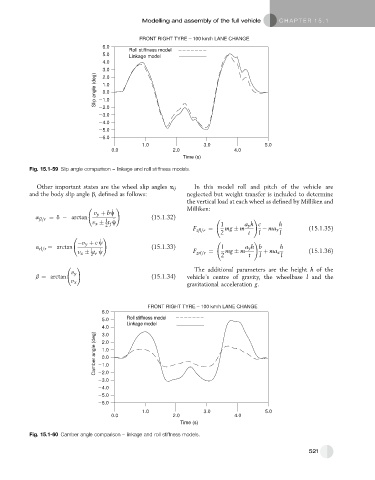
Fig. 15.1-59 Slip angle comparison – linkage and roll stiffness models.
Other important states are the wheel slip angles a ij In this model roll and pitch of the vehicle are
and the body slip angle b, defined as follows: neglected but weight transfer is included to determine
the vertical load at each wheel as defined by Milliken and
! Milliken:
_
v y þ bw
a fl=r ¼ d arctan (15.1.32) !
1 _
v x t w
2 f 1 a y h c h
F zfl=r ¼ 2 mg m t l ma x l (15.1.35)
!
_
v y þ c w !
a rl=r ¼ arctan (15.1.33) 1 a y h b h
_
1
v x t r w F zrl=r ¼ 2 mg m t l þ ma x l (15.1.36)
2
!
The additional parameters are the height h of the
v y
b ¼ arctan (15.1.34) vehicle’s centre of gravity, the wheelbase l and the
v x
gravitational acceleration g.
FRONT RIGHT TYRE – 100 km/h LANE CHANGE
6.0
_ _ _ _ _ _ _
5.0 Roll stiffness model
Linkage model __________
4.0
Camber angle (deg) 1.0
3.0
2.0
1.0
0.0
2.0
3.0
4.0
5.0
6.0
1.0 3.0 5.0
0.0 2.0 4.0
Time (s)
Fig. 15.1-60 Camber angle comparison – linkage and roll stiffness models.
521