Page 511 - Automotive Engineering Powertrain Chassis System and Vehicle Body
P. 511

Modelling and assembly of the full vehicle   C HAPTER 15.1


                                              ROLL STIFFNESS MODEL – 100 km/h LANE CHANGE
                                    40.0
                                    30.0        Track test  __  __  __  __
                                                         ___________
                                                ADAMS
                                    20.0
                                 Yaw rate (deg/s)   10.0
                                    10.0
                                     0.0


                                    20.0
                                    30.0

                                    40.0
                                                 1.0                3.0                5.0
                                       0.0                2.0                4.0
                                                             Time (s)

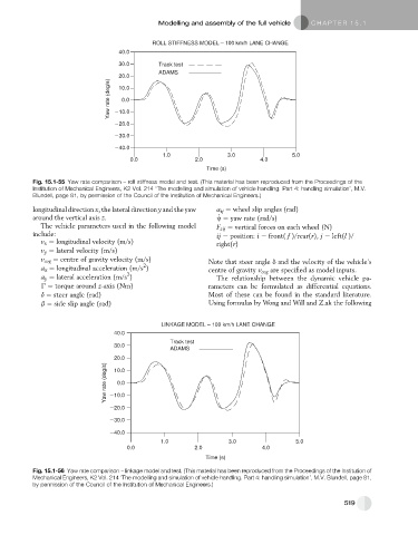
           Fig. 15.1-55 Yaw rate comparison – roll stiffness model and test. (This material has been reproduced from the Proceedings of the
           Institution of Mechanical Engineers, K2 Vol. 214 ‘The modelling and simulation of vehicle handling. Part 4: handling simulation’, M.V.
           Blundell, page 81, by permission of the Council of the Institution of Mechanical Engineers.)

           longitudinal direction x, the lateral direction y and the yaw  a ij ¼ wheel slip angles (rad)
                                                                 _
           around the vertical axis z.                          w ¼ yaw rate (rad/s)
             The vehicle parameters used in the following model  F zij ¼ vertical forces on each wheel (N)
           include:                                             ij ¼ position: i ¼ front( f )/rear(r), j ¼ left(l )/
             v x ¼ longitudinal velocity (m/s)                  right(r)
             v y ¼ lateral velocity (m/s)
             v cog ¼ centre of gravity velocity (m/s)         Note that steer angle d and the velocity of the vehicle’s
                                           2
             a x ¼ longitudinal acceleration (m/s )           centre of gravity v cog are specified as model inputs.
                                      2
             a y ¼ lateral acceleration (m/s )                  The relationship between the dynamic vehicle pa-
             G ¼ torque around z-axis (Nm)                    rameters can be formulated as differential equations.
             d ¼ steer angle (rad)                            Most of these can be found in the standard literature.
             b ¼ side slip angle (rad)                        Using formulas by Wong and Will and Z.ak the following


                                                LINKAGE MODEL – 100 km/h LANE CHANGE
                                  40.0
                                                           __  __  __  __
                                                   Track test

                                  30.0                      ___________
                                                   ADAMS
                                  20.0
                                Yaw rate (deg/s)   10.0
                                  10.0
                                   0.0


                                  20.0
                                  30.0

                                  40.0
                                                1.0                 3.0                 5.0
                                      0.0                 2.0                 4.0
                                                             Time (s)

           Fig. 15.1-56 Yaw rate comparison – linkage model and test. (This material has been reproduced from the Proceedings of the Institution of
           Mechanical Engineers, K2 Vol. 214 ‘The modelling and simulation of vehicle handling. Part 4: handling simulation’, M.V. Blundell, page 81,
           by permission of the Council of the Institution of Mechanical Engineers.)


                                                                                                      519
   506   507   508   509   510   511   512   513   514   515   516