
Page 506 - Automotive Engineering Powertrain Chassis System and Vehicle Body
P. 506
CHAP TER 1 5. 1 Modelling and assembly of the full vehicle
Fig. 15.1-47 Large body slip angles are unavailable to normal drivers except as part of an accident. Subaru WRC, Greece 2002 (courtesy
of Prodrive).
discussed based on results obtained using the four vehicle models to calculate the degrees of freedom in the model.
models described in section 15.1.4 and summarized An example is provided here for the equivalent roll
schematically again here in Fig. 15.1-52. The models stiffness model where the degrees of freedom can be
shown can be thought of as a set of models with evolving calculated as follows:
levels of elaboration leading to the final linkage model
that involves the modelling of the suspension linkages Parts 9 6 ¼ 54
and the bushes. Rev 8 5 ¼ 40
For each of the vehicle models described here it is Motion 2 1 ¼ 2
P
possible to estimate the model size in terms of the de- DOF ¼ 12
grees of freedom in the model and the number of
equations that MSC.ADAMS uses to formulate a solu-
tion. The calculation of the number of degrees of free- In physical terms it is more meaningful to describe
dom (DOF) in a system is based on the Greubler these degrees of freedom in relative terms as follows.
equation. It is therefore possible for any of the vehicle The vehicle body part has 6 degrees of freedom. The
Body slip angle
Body slip 3
angle limit
4 Car
dynamic
behaviour
1 2
Front axle lateral acceleration
Intended path
curvature
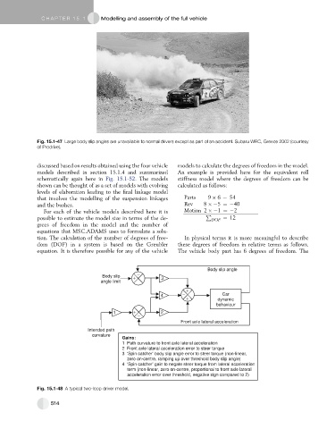
Gains:
1 Path curvature to front axle lateral acceleration
2 Front axle lateral acceleration error to steer torque
3 ‘Spin catcher’ body slip angle error to steer torque (non-linear,
zero on-centre, ramping up over threshold body slip angle)
4 ‘Spin catcher’ gain to negate steer torque from lateral acceleration
term (non-linear, zero on-centre, proportional to front axle lateral
acceleration error over threshold, negative sign compared to 2)
Fig. 15.1-48 A typical two-loop driver model.
514